Method for determining solvent permeability of films

Active Publication Date: 2007-06-28
INTERUNIVERSITAIR MICRO ELECTRONICS CENT (IMEC VZW)
View PDF2 Cites 6 Cited by
  • Summary
  • Abstract
  • Description
  • Claims
  • Application Information

AI Technical Summary

Benefits of technology

[0009]According to preferred embodiments, a simple and good method to determine the permeability of films or top coatings towards solvents such as, e.g., water, i

Problems solved by technology

The (top) coatings or thin films are typically deposited onto a substrate and can have a thickness below 1 μm, preferably from about 1 nm to 1 μm, which

Method used


Image

  • Method for determining solvent permeability of films
  • Method for determining solvent permeability of films
  • Method for determining solvent permeability of films

Examples


example 1

Ellipsometric Measurements to Determine Diffusion Rate of Water in a Hydrophilic and Hydrophobic SiCO(H) Low-k Material

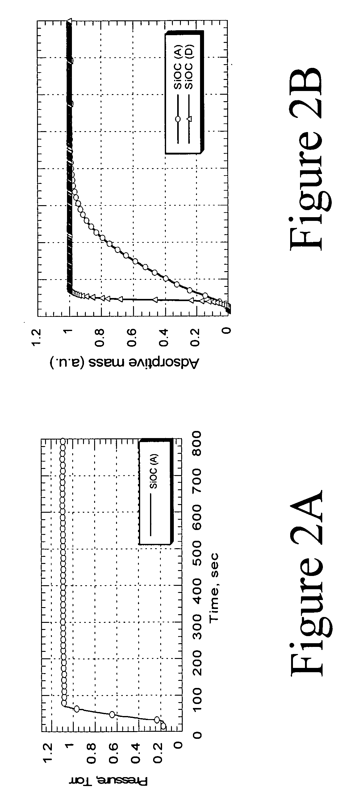
[0053]FIG. 2A illustrates the change of pressure in the pressurizable chamber as a function of time for a first SiOC material (A).

[0054]FIG. 2B shows the change in absorptive mass (solvent) as a function of time for the first SiOC material (A) and for a second SiOC material (D). The first SiOC material (A) can, according to this example, be a hydrophobic SiOC(H) low k-material. The second SiOC material (D) can, according to this example, be a (pre-treated) hydrophilic low-k SiOC(H). For the second SiOC material (D) the change in (vapor) pressure is the same as the absorbed mass of solvent. In the case of the second SiOC material (D) the diffusion rate is thus the same as the change in pressure and therefore the process is limited by absorption (not diffusion). In the first SiOC material (A), the absorption / desorption rate is much smaller than in the second SiOC mate...

example 2

Determination of the Amount of Water Permeated through a Top Coating used in Immersion Lithography Using a NCS (NanoClustered Silica) Layer as Container Layer

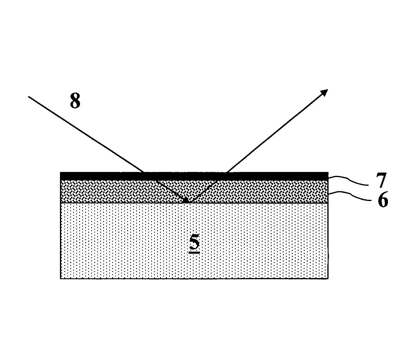
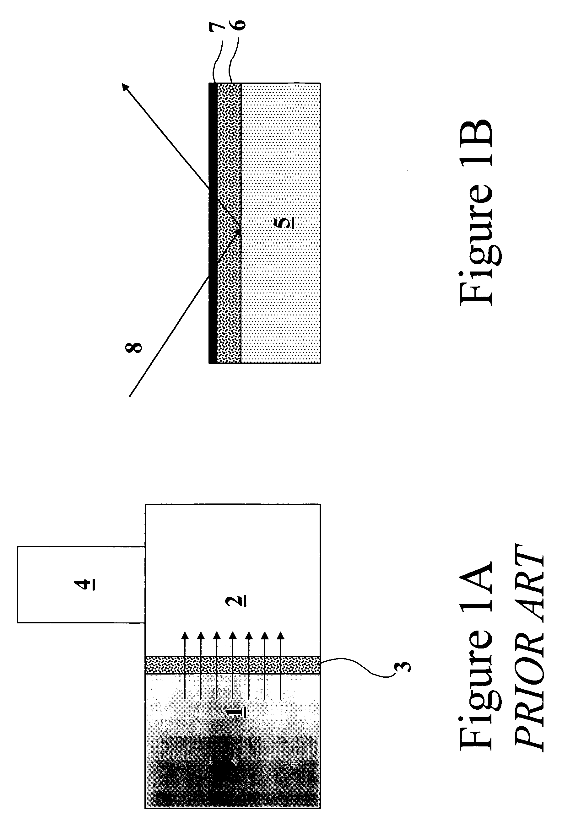
[0055]A NanoClustered Silica (NCS) layer, used in semiconductor processing as a dielectric material, is used in this experiment as an absorption or container layer 6. The NCS layer 6 is coated onto a substrate 5; the thickness of the NCS layer 6 is 400 nm and has a porosity (P) of 30%. The NCS container layer 6 is covered by a top coating 7. The top coating 7 is used in immersion lithography as a protective coating for photosensitive layers. Subsequently the container layer (NCS) 6 is completely saturated with water by transferring the substrate 5 into a pressurizable chamber, which is filled with water vapor, which diffuses through the top coating 7 (FIG. 3A, absorption region) into the NCS layer 6. Then the pressure in the chamber is pumped down very fast (dashed curve in FIG. 3B shows change of pressure) to desorb the water ...


PUM

PropertyMeasurementUnit
Pressureaaaaaaaaaa
Pressureaaaaaaaaaa
Hydrophilicityaaaaaaaaaa

Abstract

A method is disclosed to measure the permeability of films or coatings towards solvents (e.g. water). First a substrate comprising an absorption or container layer is provided, preferably the material is a porous material. To study water permeability, the porous material is hydrophilic or is made hydrophilic by means of e.g. an anneal process. To study the permeability of the film or coating, the coating is deposited on top of the porous material. The substrate comprising the film or coating on top of the absorption or container layer is then brought into a pressurizable chamber subsequently filled with the gaseous substance of the solvent (e.g. water vapor). By increasing/decreasing the vapor pressure in the chamber between zero and the equilibrium vapor pressure of the solvent used, the permeability (penetration) of solvent through the film or coating can be determined. The amount of solvent that can penetrate through the film or coating can be measured by means of ellipsometry, mass spectrometry, etc. The method of preferred embodiments of the invention can be applied to predict the water permeability of photosensitive coatings used in photolithography in semiconductor processing, which is especially important in case of immersion lithography.

Description

CROSS-REFERENCE TO RELATED APPLICATIONS[0001]This application claims the benefit under 35 U.S.C. § 119(e) of U.S. provisional application Ser. No. 60 / 753,449, filed Dec. 22, 2005, the disclosure of which is hereby expressly incorporated by reference in its entirety and is hereby expressly made a portion of this application.FIELD OF THE INVENTION[0002]The preferred embodiments are related to the field of analytical measurements; more specifically they relate to a method for determination of solvent permeability of films or coatings, in particular for films or coatings with a thickness below 1 μm.BACKGROUND OF THE INVENTION[0003]The rate at which molecules from a gaseous or liquid phase can diffuse through a sheet of material, such as a foil, membrane, cloth, fabric etc., has a substantial importance in numerous practical applications, and consequently there exists a strong demand for instruments capable of providing quantitative information about this so-called permeation process. In...

Claims


Application Information

Patent Timeline
IPC IPC(8): C23C16/52B05D3/00B05C3/00B05C11/00
CPCG01N15/082G01N15/0826G01N2015/0873
Inventor BAKLANOV, MIKHAILFOUBERT, PHILIPPE
Owner INTERUNIVERSITAIR MICRO ELECTRONICS CENT (IMEC VZW)
Why Eureka
Try Eureka