
Apparatus and method for controlling switch of satellite transponder for multibeam communication

Inactive Publication Date: 2007-06-28
ELECTRONICS & TELECOMM RES INST
View PDF9 Cites 35 Cited by
  • Summary
  • Abstract
  • Description
  • Claims
  • Application Information

AI Technical Summary

Benefits of technology

[0008] It is, therefore, an object of the present invention to provide an apparatus for controlling a switch of a satellite transponder for multibeam communication, the apparatus which can increase the output efficiency of communicated satellite electric wave signals and reuse frequencies in one-to-one earth station communication or a one-to-multi earth station communication, and a method thereof. Technical Solution
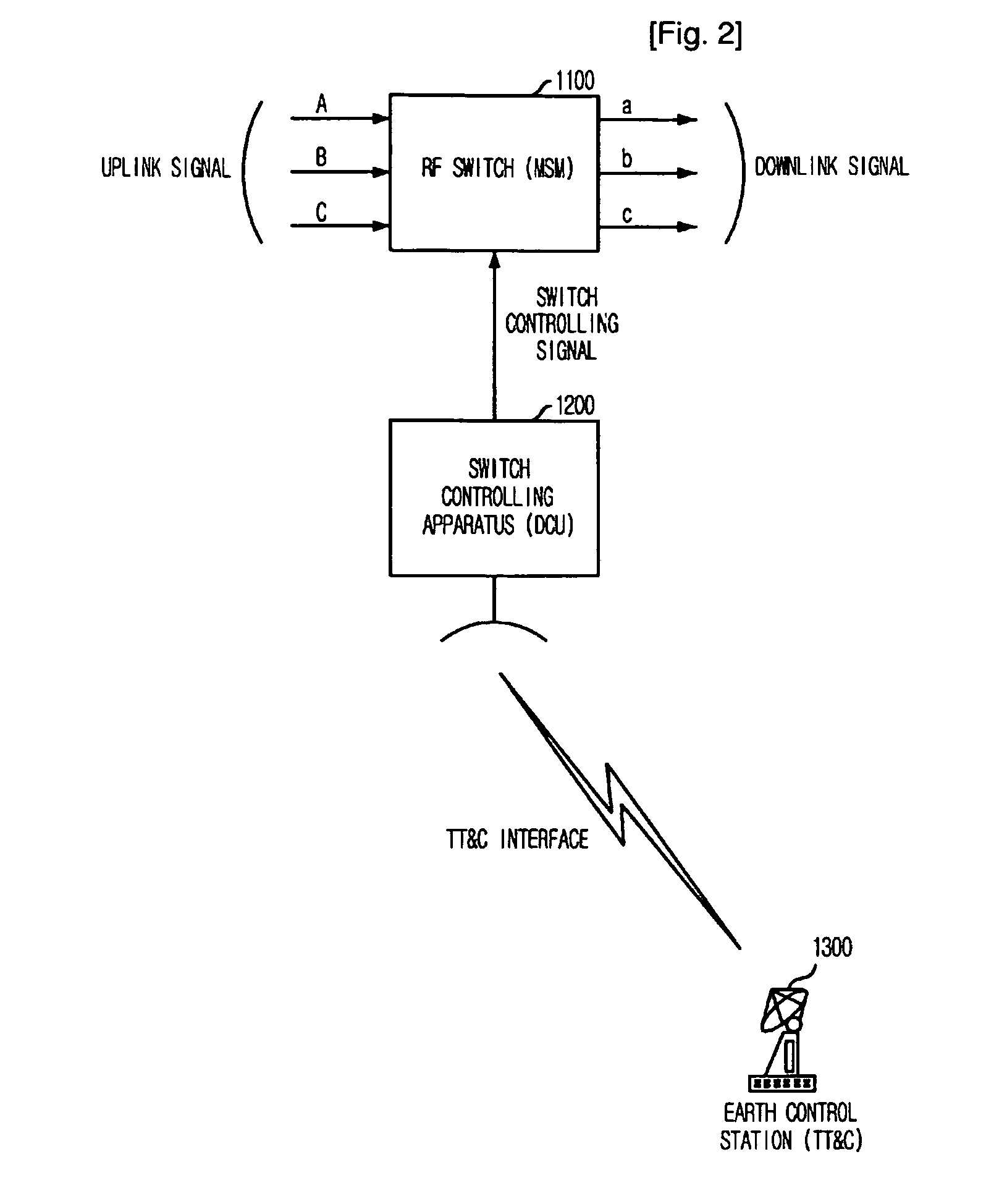
[0012] Accordingly, the present invention provides a switch controlling apparatus which controls an RF switch for multibeam switching effectively. Its dual memory structure increases system reliability and the switch controlling apparatus has an earth station interface for monitoring and controlling operation state of the switch controlling apparatus in the earth station.

Problems solved by technology

However, since a communication satellite signal wave is transmitted over a wide area, there is a problem that the satellite wave output and frequency resources are used wastefully on the part of the earth station which performs one-to-one communication.
If there is only one space switch, trouble in the space switch leads to a serious trouble of the entire system.
However, since the switch is divided into a plurality of space switches, although some of the space switches are out of order, traffics can be processed with the other space switches.
In consequences, it does not provide a function of transmitting the electric wave signals which should be transmitted from a beam area into other areas in the satellite by using a switching function.
Therefore, it cannot increase the electric power efficiency of the transponder and reuse frequencies.

Method used


Image

  • Apparatus and method for controlling switch of satellite transponder for multibeam communication
  • Apparatus and method for controlling switch of satellite transponder for multibeam communication
  • Apparatus and method for controlling switch of satellite transponder for multibeam communication

Examples


Embodiment Construction

[0017] Other objects and aspects of the invention will become apparent from the following description of the embodiments with reference to the accompanying drawings, which is set forth hereinafter.

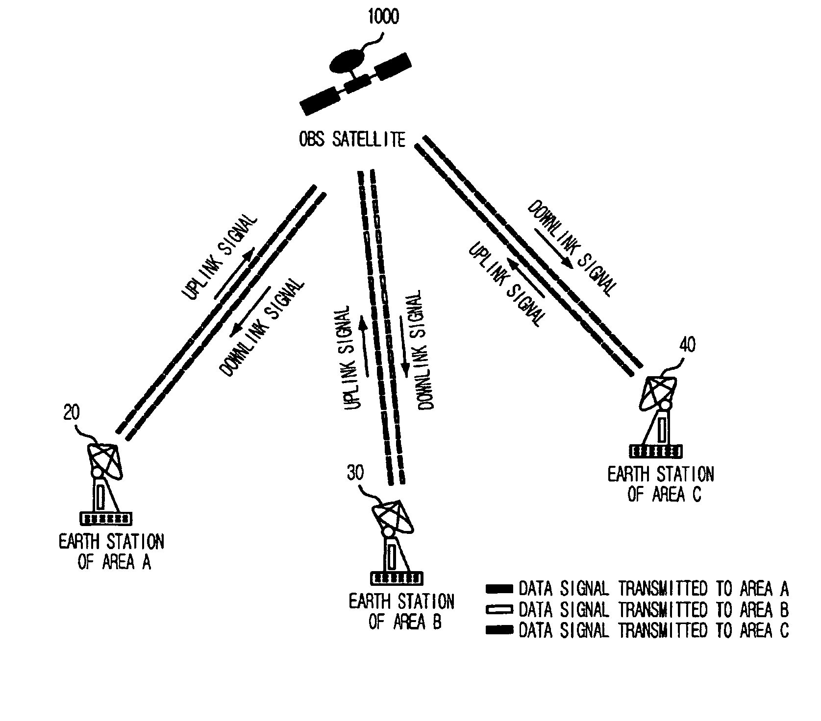
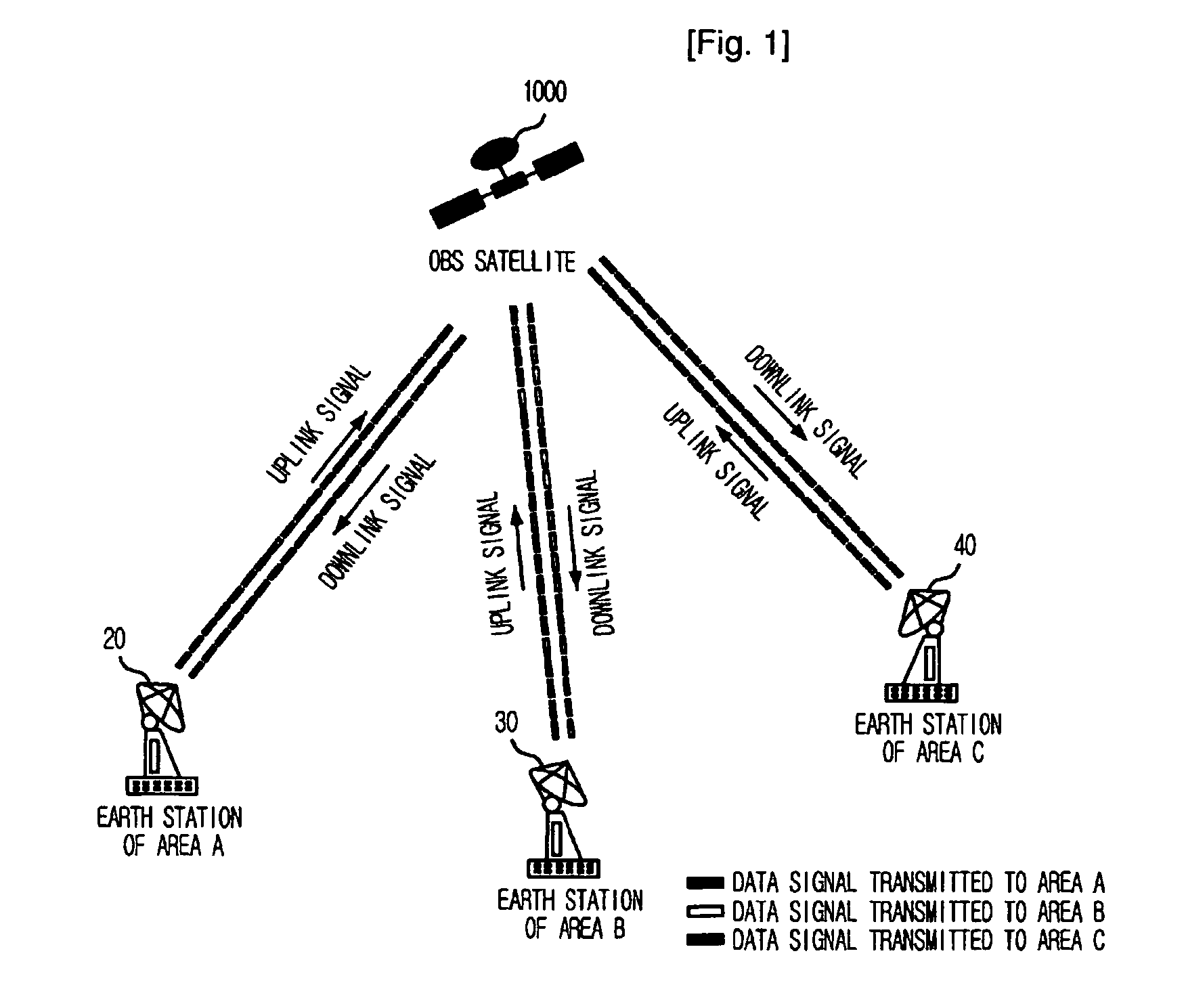
[0018]FIG. 1 is an exemplary diagram illustrating a satellite communication system for multibeam communication to which the present invention is applied.

[0019] As shown, an On-board Switch (OBS) satellite 1000 divides satellite coverage where the electric waves form the satellite can be received into a plurality of areas. For example, an earth station 20 of an area A denotes one of earth stations that is located in a beam area A of the OBS satellite 1000. An earth station B 30 of an area B and an earth station C 30 of an area C denote earth stations that are located in the beam areas B and C of the OBS satellite 1000, respectively.

[0020] The earth station 20 of the area A transmits uplink signals to the OBS satellite 1000 by performing time-division on signals (A->B and A->C) to be tran...


PUM


Abstract

Provided are an apparatus for controlling a switch of a satellite transponder for multibeam communication, and a method thereof. The apparatus and method can increase output efficiency of communicated satellite electric wave signals and reuse frequencies in one-to-one earth station communication or a one-to-multi earth station communication. The apparatus includes: an earth control station interfacing block for receiving and processing commands from an earth control station, collecting operation states of the switch controlling apparatus and reporting them to the earth control station; a reference frequency generating block for generating a reference clock needed to operate the switch controlling apparatus and generating a reference frequency based on the reference clock; and a switch controlling block for reading contents of a memory storing a switching sequence periodically, detecting and correcting errors of the contents to generate a switch control signal, and transmitting the signal to a radio frequency switch.

Description

TECHNICAL FIELD [0001] The present invention relates to an apparatus for controlling a switch of a satellite transponder for multibeam communication and a method thereof; and, more particularly, to an apparatus for controlling a switch of a satellite transponder for multibeam communication that can control an On Board Switch (OBS) of a communication satellite transponder which performs multibeam switching, and a method thereof. BACKGROUND ART [0002] Generally, a communication satellite transponder which is mounted on a communication satellite in a geostationary orbit receives an uplink signal from an earth station, converts the uplink signal into a downlink signal through signal conversion and amplification, and transmits the downlink signal back to the earth station. This function is called signal transponding. [0003] The communication satellite transponder is called a bent pipe-type transponder and it simply converts the frequency of the uplink signal inputted to the satellite, an...

Claims


Application Information

Patent Timeline
IPC IPC(8): H04B7/185
CPCH04B7/18515H04B7/2041H04B7/185
Inventor JO, JIN-HOCHOI, KYUNG-SOOEUN, JONG-WONLEE, SEONG-PAL
Owner ELECTRONICS & TELECOMM RES INST
Learn More