Arrangement at an internal combustion engine

a technology for internal combustion engines and arrangement, which is applied in the direction of machines/engines, electric devices, gearing, etc., can solve the problems that the speed as dependent on the transmission ratio and the engine speed, may not be suited to the requirements of the auxiliary unit, etc., and achieves low dependency on the engine speed, short time span, and large range

Inactive Publication Date: 2007-06-28
FORD GLOBAL TECH LLC
View PDF3 Cites 56 Cited by
  • Summary
  • Abstract
  • Description
  • Claims
  • Application Information

AI Technical Summary

Benefits of technology

[0003] Accordingly, this invention is directed to decreasing the dependency of an auxiliary unit, adapted to be driven by an internal combustion engine, upon the engine wherein an arrangement for an internal combustion engine includes a first electrical machine, a transmission comprising a planetary gear set, the planetary gear set comprising three gear parts in the form of a sun wheel, an annulus wheel, and a planet carrier, wherein the three gear parts are connected respectively to the auxiliary unit, the first electrical machine and the crankshaft.
[0004] Thereby, the first electrical machine can be used to continuously change the effective gear ratio of the planetary gear, so that the speed requirements of the auxiliary unit can be met with a low dependency on the engine speed.
[0005] Therefore, it becomes possible to run the auxiliary unit at a speed that is adapted to the operational requirements of the unit. These requirements can differ very much from the requirements of the requirements on the engine. For example, in a vehicle it can be desired to run an A / C compressor at a constant speed, while the engine is required, due to intensive driver requests and demanding road conditions, to change speed within a very large range and within short time spans. An embodiment of the present invention can allow for an auxiliary device to run at constant speed while the engine speed is changing within a large interval. This will allow for auxiliary units and auxiliary systems to be designed without taking engine speed fluctuations into account, or reducing consideration for such fluctuations. In turn, this will improve the performance and / or reduce complexity of auxiliary systems. In other words, the independent operation of the auxiliary unit, provided by the invention, is very advantageous in cases where the auxiliary unit itself drives a device or a system which has operational parameters with requirements that are independent of the engine speed.
[0006] In one embodiment of the present invention, the auxiliary unit is a compressor for an air conditioning system. An air conditioning system, having requirements that are essentially independent of the engine requirements, can thereby maintain an operation with limitations of engine operation dependency largely reduced.
[0007] In another embodiment, the auxiliary unit is a supercharger in a homogenous charge compression ignition (HCCI) engine. In a HCCI engine the arrangement according to the present invention has very large advantages. As is known in the art, in a conventional HCCI engine, when the load increases, the ignition mode has to be changed from homogenous charge compression ignition to, depending on the engine type, spark ignition or traditional compression ignition. However, due to the favourable fuel consumption characteristics of the HCCI mode, it is advantageous to maintain this mode also at higher loads. With the arrangement according to this embodiment of the invention, it is possible to provide a high speed of the supercharger, even if the engine speed is relatively low. This means that the pressure (total mass) of the air / fuel mixture and dilution ratio with EGR (Exhaust Gas Recirculation) can be increased to maintain the HCCI mode when the engine load increases. Also, this will decrease the number of ignition mode switches in a HCCI engine.

Problems solved by technology

A problem is that the speed of the auxiliary unit, as dependent on the transmission ratio and the engine speed, may not be suited to the requirements of the auxiliary unit.

Method used


Image

  • Arrangement at an internal combustion engine
  • Arrangement at an internal combustion engine
  • Arrangement at an internal combustion engine

Examples


Embodiment Construction

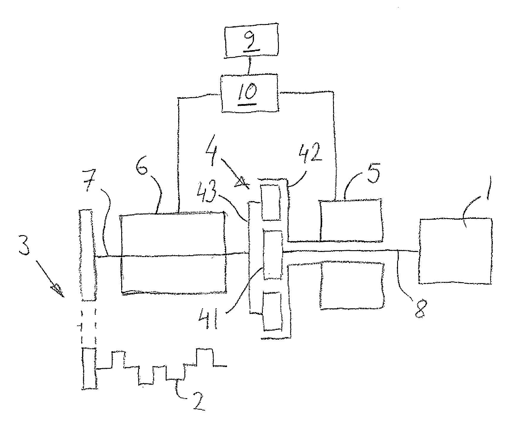
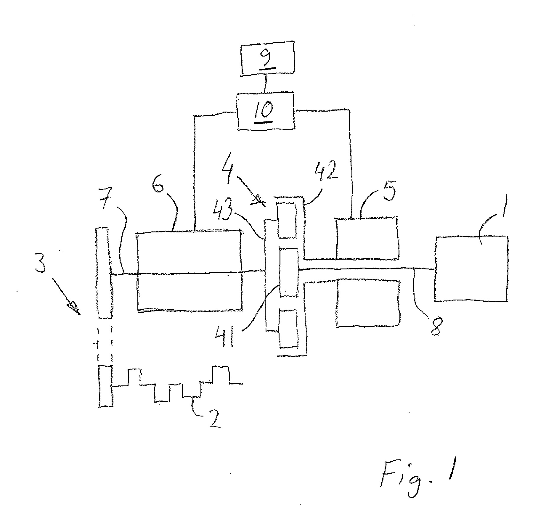
[0013]FIG. 1 shows a schematic view of an arrangement at an internal combustion engine with a crankshaft 2, comprising an auxiliary unit 1, a transmission 3, 4, a first electrical machine 5 and a second electrical machine 6. In this example, the auxiliary unit 1 is a compressor for an air conditioning system of a vehicle equipped with an internal combustion engine. However, the auxiliary unit 1 could also be a coolant pump, hydraulic pump (for power steering, active suspension, etc.), vacuum pump (for brakes etc), fuel pump (for fuel feed or high pressure injection), oil pumps (for transmission and engine lubrication), or any other auxiliary apparatus. As described closer below, in another embodiment, the auxiliary unit is a supercharger in a homogenous charge compression ignition (HCCI) engine.

[0014] The transmission comprises a first transmission part 3, (in FIG. 1 partially indicated with broken lines), connecting the crankshaft 2 with a first shaft 7. The first transmission par...


PUM


Abstract

The invention relates to an arrangement at an internal combustion engine, comprising an auxiliary unit and a transmission, the auxiliary unit being adapted to be driven by a crankshaft of the engine via the transmission, characterized in that it comprises a first electrical machine, in that the transmission comprises a planetary gear set, comprising three gear parts in the form of a sun wheel, an annulus wheel, and a planet carrier, and in that the three gear parts are connected respectively to the auxiliary unit, the first electrical machine and the crankshaft.

Description

TECHNICAL FIELD [0001] The present invention relates to an arrangement for an internal combustion engine, comprising an auxiliary unit and a transmission, the auxiliary unit being adapted to be driven by a crankshaft of the engine via the transmission. BACKGROUND AND SUMMARY OF THE INVENTION [0002] Auxiliary units of an internal combustion engine are usually driven by the engine crankshaft via some sort of transmission. The engine could be mounted in a vehicle, where the engine speed is dependent on the operational situation of the vehicle. A problem is that the speed of the auxiliary unit, as dependent on the transmission ratio and the engine speed, may not be suited to the requirements of the auxiliary unit. As an example, where the auxiliary unit is a compressor for an air conditioning system of a vehicle, the requirements of the A / C system, and therefore the A / C compressor speed is substantially independent of the requirements of the engine speed. [0003] Accordingly, this invent...

Claims


Application Information

Patent Timeline
Patent Type & Authority Applications(United States)
IPC IPC(8): F16H3/72B60K6/485
CPCB60K6/485B60K25/02B60W10/08B60W10/30B60W20/00F02B39/04F02B39/10F02B67/04F02B67/10F16H3/727F16H2037/088Y02T10/6226B60L2220/50B60L50/10Y02T10/62Y02T10/64Y02T10/7072B60K6/38B60W10/115Y02T10/70
Inventor SALLSTROM, GORAN
Owner FORD GLOBAL TECH LLC
Why Eureka
Try Eureka