Ultrasonic flowmeter, wedge for ultrasonic flowmeter, method for setting ultrasonic transmitting/receiving unit, and ultrasonic transmitting/receiving unit

a technology of ultrasonic flowmeter and ultrasonic transmitting/receiving unit, which is applied in the direction of volume/mass flow measurement, measurement device, measurement, etc., can solve the problems of lowering the signal strength of the signal returned from the reflector to be measured, affecting measurement accuracy, and incorrect measurement value, so as to improve measurement accuracy and simplify installation , the effect of efficient ultrasonic penetration

Inactive Publication Date: 2007-07-05
THE TOKYO ELECTRIC POWER CO INC
View PDF10 Cites 22 Cited by
  • Summary
  • Abstract
  • Description
  • Claims
  • Application Information

AI Technical Summary

Benefits of technology

[0114] According to the present invention, it becomes possible to provide a technology contributing to further improved measurement accuracy for the “clamp-on” type ultrasonic flowmeter.
[0115] Firstly, it has enabled the provision of a technology contributing to efficient ultrasonic penetration through both the wedge and the pipe wall surface and more acculate measurement of flow rate.
[0116] Secondly, it has made positioning the wedge supporting the ultrasonic transmitting and receiving device serving as an emission and receiver to the pipe easier, and has simplified installation. Furthermore, it has become possible to make adjustments work more easily at the time of inspection and to easily maintain a suitable incident angle of the ultrasonic transmitting and receiving device to the pipe. It was also possible to provide a method of setting such an ultrasonic transmitting and receiving device, an ultrasonic transmitting and receiving unit and an ultrasonic flowmeter.
[0117] Thirdly, it has also possible to provide a wedge member used to an ultrasonic transducer transmitting the pulse width of an ultrasonic pulse as its performance and a method of installing the wedge member irrespective of a pipe caliber and a shape.
[0118] Fourthly, in an ultrasonic flowmeter providing an emission and a receiver as an ultrasonic transmitting and receiving device, it has also become possible to provide a technology to restrain measurement errors caused by noise generated from the emission and to measure a flow rate more accurately.

Problems solved by technology

When the ultrasonic wave can not permeate through the wedge and the pipe wall perfectly, noise due to reflection from the pipe wall is generated, which results in a lowering of the signal strength of the signal returned from the reflector to be measured.
In such a case, it requires working for correction of the value by actually measuring the pulse width or it often results in an incorrect measurement value due to omitting of actual measurement and correction.
That is, there is a fear that the measurement accuracy is influenced by the magnitude of the contact area.
However, since there are a plenty of varieties in size and shape of the caliber of piping, sometimes it may not match previously prepared wedges.
Even when the size and shape of the caliber of piping to be measured are known in advance, according to conditions of coating on the pipe surface or deterioration with time (for instance, degradation of coating or corrosion), there is a fear that a wedge member prepared according to the given data does not match.
However, a fixation work by positioning the composition surface of the wedge to the outer surface of the piping without inclination accurately requires a very long time and a skill.
Even when it can be accurately installed once, deformation due to aging, thermal deformation due to a high temperature fluid, and the like happen to the wedge or the piping, which may cause a bad influence to the measurement accuracy.
But, even when the drive signal is suspended, mechanical vibration still remains.
The vibration left after the drive signal is suspended works as noise to the switched receiver.
As a result, in a step of flow velocity calculating means, error which seems to be caused by the noise as shown in FIG. 9 is generated.
However, when the pipe diameter is small, it is found that it causes negligible measurement errors.

Method used


Image

  • Ultrasonic flowmeter, wedge for ultrasonic flowmeter, method for setting ultrasonic transmitting/receiving unit, and ultrasonic transmitting/receiving unit
  • Ultrasonic flowmeter, wedge for ultrasonic flowmeter, method for setting ultrasonic transmitting/receiving unit, and ultrasonic transmitting/receiving unit
  • Ultrasonic flowmeter, wedge for ultrasonic flowmeter, method for setting ultrasonic transmitting/receiving unit, and ultrasonic transmitting/receiving unit

Examples


Embodiment Construction

[0119] Hereinafter, the present invention will be further explained in detail based on an embodiment and drawings. Drawings used here are from FIG. 1 to FIG. 5, FIG. 7 and FIG. 8.
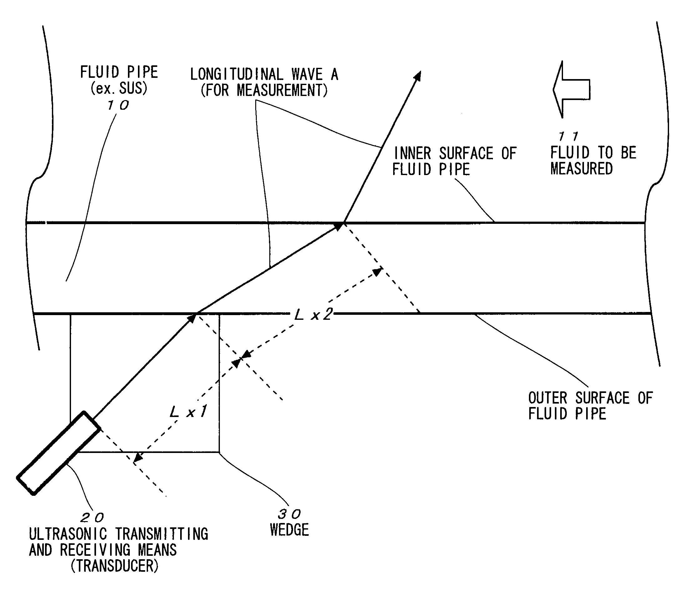
[0120] (FIG. 1)

[0121] In an ultrasonic flowmeter to measure a flow rate in a fluid pipe 10 through which a fluid to be measured 11 flows, FIG. 1 is provided with an ultrasonic transmitting and receiving means (transducer 20) serving as a receiver receiving ultrasonic echoes reflected from a measurement region of ultrasonic pulses incident into the fluid to be measured 11. The transducer 20 is fixed at a prescribed portion on the pipe 10 by a plastic (for instance, made of acryl resin) wedge 30.

[0122] The transducer 20 serves as an ultrasonic transmitter transmitting ultrasonic pulses of a prescribed frequency (reference frequency) along a measuring line to the fluid to be measured 11, and as a flow velocity distribution measuring means to receive ultrasonic echoes reflected from the measurement region of...


PUM


Abstract

In order to provide a technology in an ultrasonic flowmeter to efficiently penetrate through both of a wedge and a fluid pipe surface so as to contribute to more accurate measurement of a flow rate. An ultrasonic flowmeter includes an ultrasonic transmitter for launching ultrasonic pulses of a predetermined frequency into the fluid to be measured in fluid pipe from an ultrasonic transducer along a measurement line; a flow velocity distribution measurement means for measuring flow velocity distribution of the fluid to be measured in a measurement region by receiving ultrasonic echoes (reflection wave A) reflected from the measurement region among the ultrasonic pulses incident into the fluid to be measured; and a flow rate operation means for operating a flow rate of the fluid to be measured in the measurement region based on the flow velocity distribution of the fluid to be measured, and a clamp-on type is adopted. A condition to make both a distance from the ultrasonic transmitter in the wedge to the outer surface of the liquid pipe and the wall width of the fluid pipe be an integral multiple of λ/2 of the frequency used should be satisfied.

Description

TECHNICAL FIELD [0001] The present invention relates to an ultrasonic flowmeter possible to instantaneously measure a flow rate of a fluid to be measured time-dependently from flow velocity distribution in a measurement region and a technology relating to the above-described flowmeter BACKGROUND ART [0002] Various technologies have been proposed for a Doppler ultrasonic flowmeter which can measure a flow rate without contacting fluid to be measured (for instance, Japanese Patent Application Laid-open No. 2000-97742) [0003] Patent Document 1: Japanese Patent Application Laid-open No. 2000-97742 [0004] The above-described technology will be explained concretely. The Doppler ultrasonic flowmeter disclosed in the above-described document determines a flow rate of a fluid to be measured provided with: an ultrasonic transmission means for launching ultrasonic pulses having a predetermined frequency from an ultrasonic transducer into the fluid to be measured in piping for a fluid (for inst...

Claims


Application Information

Patent Timeline
Patent Type & Authority Applications(United States)
IPC IPC(8): G01F1/66
CPCG01F1/663
Inventor MORI, MICHITSUGUTEZUKA, KENICHITEZUKA, HIDEAKI
Owner THE TOKYO ELECTRIC POWER CO INC
Why Eureka
Try Eureka