Superconducting magnet and magnetic resonance imaging apparatus using the same

Active Publication Date: 2007-07-05
HITACHI LTD +1
View PDF24 Cites 8 Cited by
  • Summary
  • Abstract
  • Description
  • Claims
  • Application Information

AI Technical Summary

Benefits of technology

[0009] An aspect of the present invention provides a superconducting magnet and a magnetic resonance imaging apparatus using the same, the superconducting magnet including: first and second torus coolant containers substantially symmetrically, vertically arranged to have a space and a symmetrical plane therebetween for storing a coolant, each of the first and second torus coolant containers including therein a main coil bobbin with a main coil for generating a measurement magnetic field, a shield coil bobbin with a shield coil for generating a shielding magnetic field for suppressing outside leak of the measurement magnetic field, a plate member vertically reinforced at a plane thereof opposite to a plane thereof facing the symmetrical plane for supporting the shield coil bobbin and the main coil bobbin, wherein the main coil bobbin is further supported by the shield coil bobbin, to cause the main coil to generate the measurement magnetic field having a substantially uniform m

Problems solved by technology

In other words, MRI apparatus having a large size is costly in carrying the MRI app

Method used


Image

  • Superconducting magnet and magnetic resonance imaging apparatus using the same
  • Superconducting magnet and magnetic resonance imaging apparatus using the same
  • Superconducting magnet and magnetic resonance imaging apparatus using the same

Examples


Example

FIRST EMBODIMENT

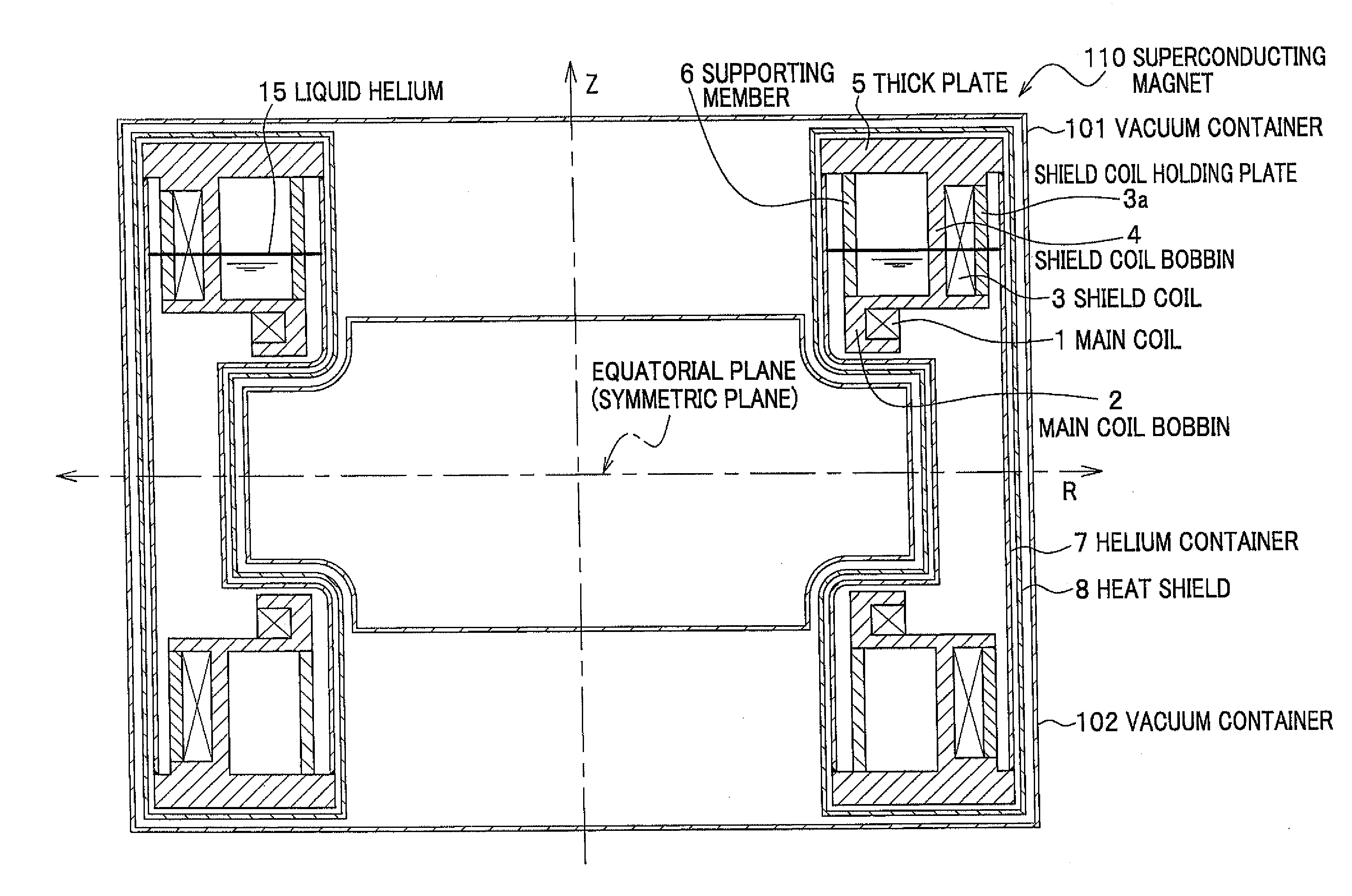
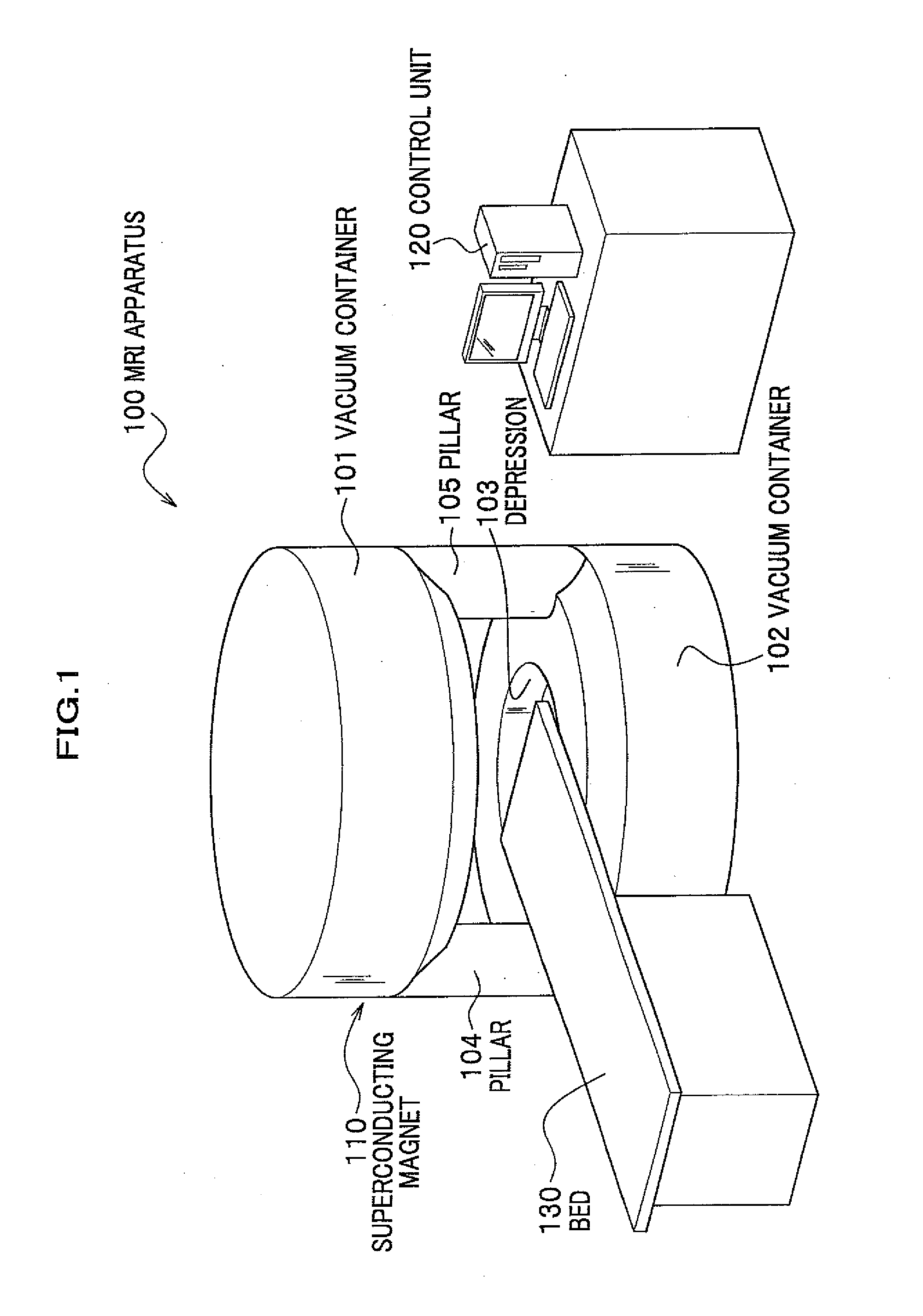
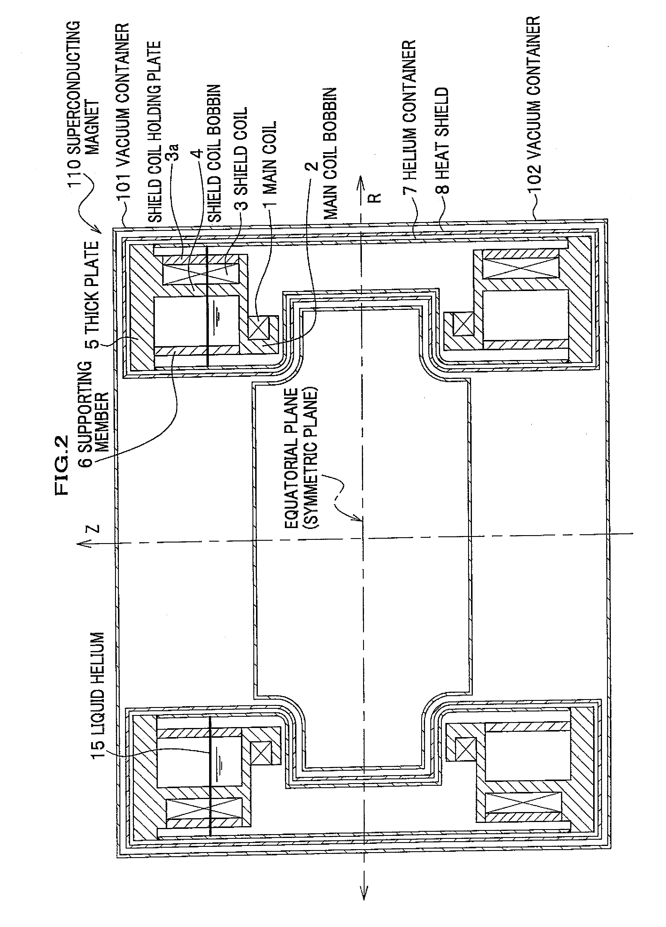
[0029]FIG. 1 shows an outline of an MRI apparatus employing a superconducting magnet according to an exemplary embodiment of the present invention. FIG. 2 shows a cross-sectional structure of the superconducting magnet including pillars of the MRI apparatus shown in FIG. 1.

[0030] As shown in FIG. 1, the MRI apparatus 100 includes two torus vacuum containers 101 and 102 vertically spaced in a symmetrical manner, connected to each other through pillars 104 and 105 for supporting the vacuum container 101. The space between the torus vacuum containers 101 and 102 is provided for measurement by the MRI apparatus 100 and allows a tip of a bed 130 supporting a subject such as a patient to be inserted thereinto.

[0031] The insides of the vacuum containers 101 and 102 are kept in vacuums with air-tight sealing to prevent heat from invading thereinto due to conduction and convection. The vacuum containers 101 and 102 house a coolant container (hereinafter referred to as a he...

Example

SECOND EMBODIMENT

[0044]FIG. 4 shows an example of a cross-sectional structure according to a second embodiment, viewed when the torus helium container 7 is cut on the plane perpendicular to circumferential direction thereof. The superconducting magnet 110 and the MRI apparatus 100 according to the second embodiment are substantially the same as those according to the first embodiment. In this and the following embodiments, the same parts as those in the first embodiment are designated with the same references and thus detailed descriptions will be omitted.

[0045] As shown in FIG. 4, in the second embodiment, the shield bobbin 4 is integrally molded with the thick plate 5 by casting or the like, but the main coil bobbin 2 are molded discretely from the thick plate 5. The main coil bobbin 2 is fixed to the shield coil bobbin 4, for example, with a fixing metal member 10 and bolts. The supporting member 6 may be molded integrally with the coil bobbin 2 and may be welded to the thick p...

Example

THIRD EMBODIMENT

[0049]FIG. 5A shows an example of a cross-sectional structure according to a third embodiment. FIG. 5B is a perspective view showing an assembling process of parts including the shield coil bobbin 4 and the main coil bobbin 2.

[0050] In the third embodiment, as shown in FIGS. 5A and 5B, the main coil bobbin 2 has a plurality of (for example, six) protruding parts 2a equi-distantly arranged on an outer circumference thereof. On the other hand, a face of the shield coil bobbin 4 on a side of the equatorial plane, i.e., a bottom face thereof in FIG. 5B, has hooks 4a (of which the number as that of the protruding parts 2a) for allowing the protruding parts 2a spaced at the same distance on an outer circumference thereof to be fitted in recesses of the hooks 4a for fixing.

[0051] In this structure, a sum of a pair of the protruding parts 2a and the hooks 4a in length is shorter than an interval (pitch) of two adjacent hooks 4a. For example, if six protruding parts 2a and...


PUM


Abstract

A superconducting magnet includes: first and second torus coolant containers substantially symmetrically, vertically arranged to have a space and a symmetrical plane therebetween for storing a coolant. Each of the first and second torus coolant containers includes therein a main coil bobbin with a main coil for generating a measurement magnetic field, a shield coil bobbin with a shield coil for generating a shielding magnetic field for suppressing outside leak of the measurement magnetic field, a plate member vertically reinforced at a plane thereof opposite to a plane thereof facing the symmetrical plane for supporting the shield coil bobbin and the main coil bobbin. The main coil bobbin is further supported by the shield coil bobbin, to cause the main coil to generate the measurement magnetic field having a substantially uniform magnetic field intensity at a middle region of the space. A magnetic resonance imaging apparatus using the superconducting magnet is also disclosed.

Description

CROSS REFERENCE TO RELATED APPLICATIONS [0001] The present application claims benefit of the filing date of Japanese patent application No. 2006-000834 filed on Jan. 5, 2006, and Japanese patent application No. 2006-190146 filed on Jul. 11, 2006, which are incorporated herein by reference. [0002] 1. Field of the Invention [0003] The present invention relates to a superconducting magnet and a magnetic resonance imaging apparatus using the same. [0004] 2. Description of the Related Art [0005] An open type of MRI (Magnetic Resonance Imaging) apparatus free from a closed sensation is known. The open type of MRI apparatus includes torus helium containers filled with liquid helium symmetrically, vertically arranged to provide a space for a measurement subject and bobbins (coil bobbins) with superconducting coils housed therein, respectively. [0006] Such an MRI apparatus generally has a structure in which a supporting member supports the coil bobbins, and the supporting member and the coil...

Claims


Application Information

Patent Timeline
IPC IPC(8): H01F6/00
CPCG01R33/3806G01R33/421G01R33/3815
Inventor WATANABE, HIROYUKIKAWAMURA, JUNCHIBA, TOMOOYAMAZAKI, MIKITAKIZAWA, TERUHIRO
Owner HITACHI LTD
Why Eureka
Try Eureka