Networked RF tag for tracking baggage

Active Publication Date: 2007-07-05
VISIBLE ASSET INC
View PDF23 Cites 98 Cited by
  • Summary
  • Abstract
  • Description
  • Claims
  • Application Information

AI Technical Summary

Benefits of technology

[0031] Preferably, the tag's first major surface can be provided with the aforesaid key buttons, which can have frictional (e.g. rubberized) surfaces for reducing slippage with resp

Problems solved by technology

A stand-alone transmitting tag with its own transmitter, instead of modulation of a reflective high frequency signal would consume far too much power, for these long range applications.
In most tracking applications a standalone two way transmitter and receiver as opposed to a transponder based system used in RF Tags and RFID tags would have too many disadvantages: too expensive, limited range, and require complex transmission RF circuitry, including crystals, and have high power consumption since all transmission power must come from the tag as opposed to the reader's interrogation signal.
A major disadvantage of all transponder based tag designs is that special anti-collision methods (see U.S. Pat. Nos. 6,377,203; 6,512,478; 6,354,493; 5,519,381, all incorporated herein by reference) must be used to read more than one tag within a reader's transmitted field, or alternatively a short range reader must be used to individually address each tag wit

Method used


Image

  • Networked RF tag for tracking baggage
  • Networked RF tag for tracking baggage
  • Networked RF tag for tracking baggage

Examples


application examples

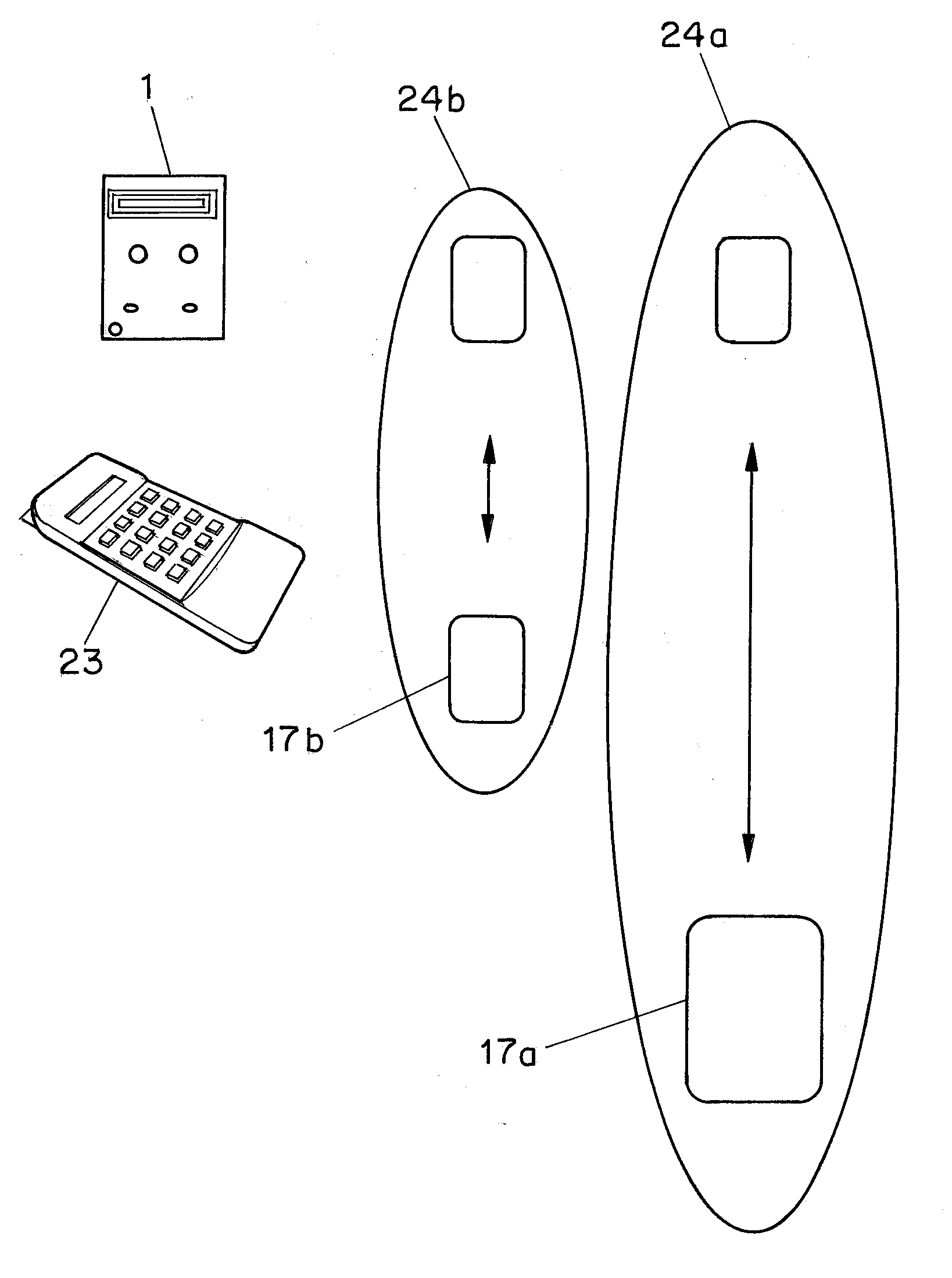
[0080] The simplest application in use of the tag may be simply as a recording of shipping information. Many shipper's have far too low volume of packages to be shipped (three to four week inventory) to justify placing a full shipping system. The average cost for such a system, particularly if it includes a printer, may be thousands of dollars. The same customers however often refuse to fill out a paper waybill. This NRF tag system simplifies shipping for low volume shippers. In its simplest form, this can provide a very low-cost shipping system to low volume shippers, and reduce cost for the courier, and provide enhanced ability to sort, track and bill the customer.

[0081] In this example the low volume shipper would be provided a hand-held with a low-cost modem built into the cradle. The hand-held can dial out a phone line to a centrally located server, provide the server with information about shipments and also receive updates as well as a customer list. The shipper would simply...


PUM


Abstract

The invention disclosed provides a method, system, and associated tag for detection and tracking of inanimate and animate objects. The novel method broadly comprises the steps of: a) attaching a low radio frequency detection tag to each of the objects, each tag comprising a tag antenna operable at a low radio frequency not exceeding 1 megahertz (preferably not exceeding 300 kilohertz), a transceiver operatively connected to the tag's antenna, the transceiver being operable to transmit and receive data signals at the low radio frequency, a data storage device operable to store data comprising identification data for identifying said detection tag, a programmed data processor operable to process data received from the transceiver and the data storage device and to send data to cause the transceiver to emit an identification signal based upon the identification data stored in said data storage device, and an energy source for activating the tag's transceiver and data processor; b) storing, in the data storage device of each tag, shipping data selected from object description data, address-of-origin data, destination address data, object vulnerability data, and object status data; c) commingling the objects in a repository selected from a warehouse and a truck, the repository being provided with at least one large loop field antenna operable at said low radio frequency; the field antenna being disposed at a distance from each object that permits effective communication therewith at the low radio frequency, d) reading the identification data and shipping data from the transceiver of each tag by interrogating all tags commingled in said repository with data signals, such as specific IP addresses or other identification codes, via said field antenna; and e) transmitting the identification data and shipping data from each tag to a central data processor to provide a tally of the objects in said repository.

Description

CROSS-REFERENCE TO RELATED APPLICATIONS [0001] This application is a continuation-in-part of U.S. application Ser. No. 11 / 276,216, filed Feb. 17, 2006, which is a continuation of U.S. application Ser. No. 10 / 820,366, filed Apr. 8, 2004, which application claims the benefit of Provisional Application No. 60 / 461,562, filed Apr. 9, 2003, each of which is incorporated herein by reference for all purposes. This application claims the benefit of Provisional Application No. 60 / 706,586, filed Aug. 8, 2005, which is incorporated herein by reference for all purposes. Related application Ser. No. 11 / 162,907, filed Sep. 28, 2005, is incorporated herein by reference for all purposes.FIELD OF THE INVENTION [0002] This invention relates to a system and method for detecting and tracking packages, freight, animals, people, and other animate and inanimate objects. The invention also relates to novel radio frequency detection tags which are capable of communicating data, such as identification and pos...

Claims


Application Information

Patent Timeline
IPC IPC(8): G08B13/14G08B1/08G08B5/22
CPCA01K11/004A01K11/008A01K15/021G06K17/00G06K19/077G07C9/00111G06Q10/08G06Q10/087G06Q20/203G06Q50/02G06Q50/30G06K2017/0045G07C9/28
Inventor AUGUST, JASONWATERHOUSE, PAULSTEVENS, JOHN K.VERGE, CHRISTOPHER W.VANDENBERG, MICHAEL J.TRUONG, KENNETH
Owner VISIBLE ASSET INC
Why Eureka
Try Eureka