Frequency agile transmitter and receiver architecture for dwdm systems

a transmitter and receiver technology, applied in the field of optical communication systems, can solve the problems of filter-based demultiplexers, coherent optical receivers suffer a limitation, and the channel plan of the system cannot be changed,

Inactive Publication Date: 2007-07-05
CIENA
View PDF10 Cites 69 Cited by
  • Summary
  • Abstract
  • Description
  • Claims
  • Application Information

AI Technical Summary

Problems solved by technology

Filter-based demultiplexers suffer a disadvantage that their design is tightly related to the channel plan of the communications network.
Consequently, the channel plan of the system cannot be changed without also replacing every involved optical demultiplexer in the network.
However, coherent optical receivers suffer a limitation in that their narrow-band performance renders them highly sensitive to carrier offset and phase noise.
As the channel frequency shifts away from this predetermined value (i.e., as the carrier offset increases), data recovery performance degrades rapidly.
Phase noise in either the LO or received optical signals appears as noise in the IF signal, and degrades receiver performance.
This requirement dramatically increases the cost of both transmitters and receivers.
As a result, coherent optical receivers are not commonly utilized in modern optical communications networks.

Method used


Image

  • Frequency agile transmitter and receiver architecture for dwdm systems
  • Frequency agile transmitter and receiver architecture for dwdm systems
  • Frequency agile transmitter and receiver architecture for dwdm systems

Examples


Embodiment Construction

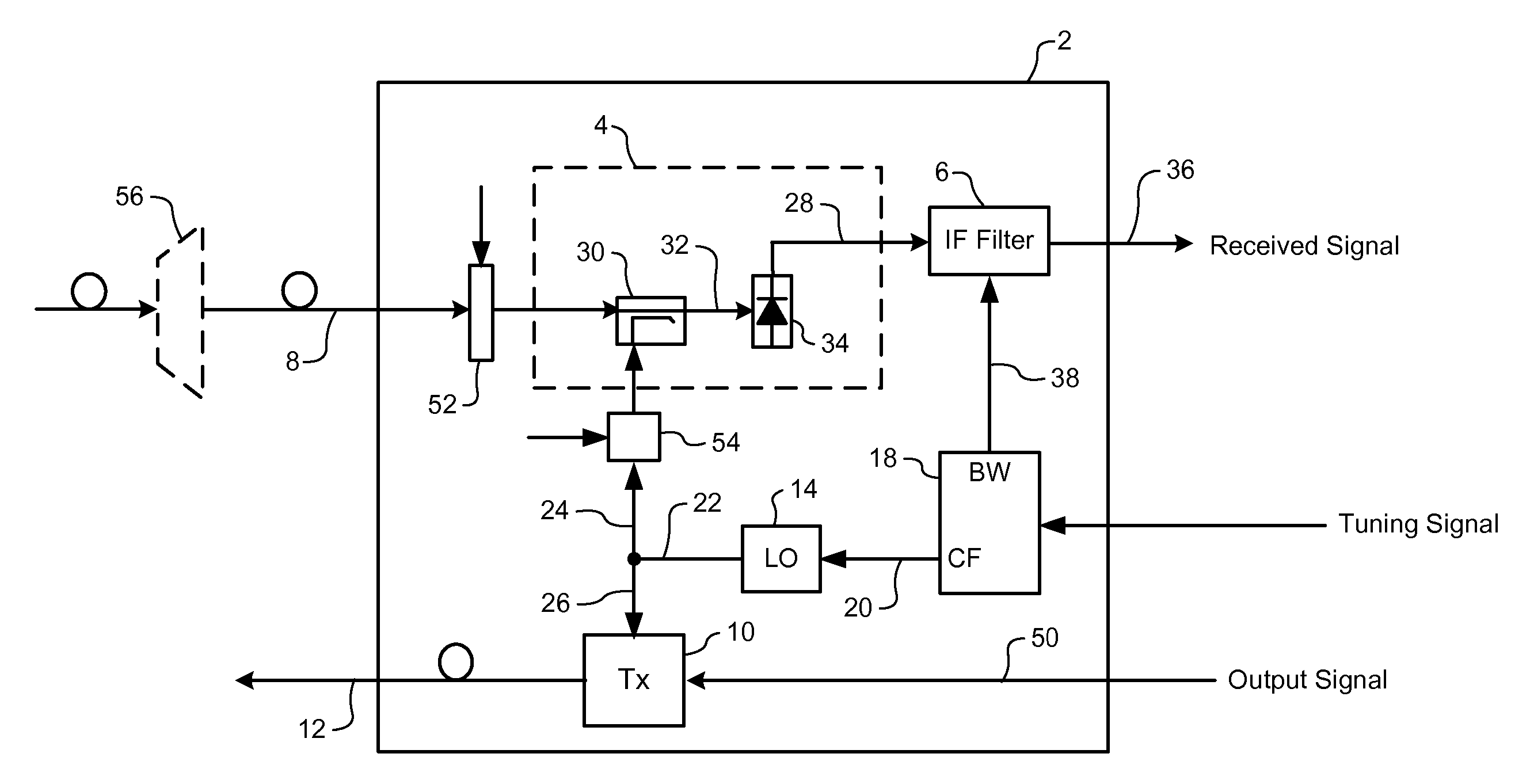
[0027] The present invention provides a frequency agile optical transceiver for transmitting and receiving data traffic through an arbitrary channel of a broadband optical signal. FIG. 1 is a block diagram schematically illustrating principal elements of a frequency agile optical transceiver in accordance with a first embodiment of the present invention.

[0028] As shown in FIG. 1, a frequency agile optical transceiver 2 in accordance with the present invention generally comprises a coherent optical receiver 4 cascaded with a controllable IF filter 6 for selectively receiving traffic of a desired “target” wavelength channel of an inbound broadband optical signal 8; an optical transmitter 10 for generating an outbound optical channel signal 12 for transmission; a shared local oscillator (LO) 14 for supplying a local oscillator optical signal 22 to both the coherent optical receiver 4 and the optical transmitter 10; and a controller 18 for controlling performance of both the controllab...


PUM


Abstract

A frequency-agile optical transceiver includes a shared local oscillator (LO), a coherent optical receiver and an optical transmitter. The LO operates to generate a respective LO optical signal having a predetermined LO wavelength. The coherent optical receiver is operatively coupled to the LO, and uses the LO signal to selectively receive traffic of an arbitrary target channel of an inbound broadband optical signal. The optical transmitter is also operatively coupled to the LO, and uses the LO to generate an outbound optical channel signal having a respective outbound channel wavelength corresponding to the LO wavelength.

Description

CROSS-REFERENCE TO RELATED APPLICATIONS [0001] This application is a divisional application of U.S. patent application Ser. No. 10 / 457,527 filed Jun. 10, 2003.MICROFICHE APPENDIX [0002] Not Applicable. TECHNICAL FIELD [0003] The present invention relates to optical communications systems, and in particular to a frequency agile transmitter and receiver architecture for Dense Wavelength Division Multiplexed (DWDM) communications systems. BACKGROUND OF THE INVENTION [0004] Optical communications networks are becoming increasingly popular for data transmission due to their high bandwidth capacity. Typically, a bit-stream is encoded (e.g., using On-Off-Keying—OOK) to generate sequential symbols that are conveyed through a communications channel by a respective optical channel signal. In most cases, the optical channel signal is generated by a narrow-band optical source (e.g., a narrow-band laser) tuned to a desired channel wavelength. At a receiving end of the communications channel, an ...

Claims


Application Information

Patent Timeline
Patent Type & Authority Applications(United States)
IPC IPC(8): H04B10/00
CPCH04B10/50H04B10/60H04B10/614H04B10/6151H04J14/06H04B10/64H04J14/02H04J14/0224H04B10/63
Inventor MCNICOL, JOHN D.WU, KUANG TSAN T.COMEAU, ADRIEN A.
Owner CIENA
Why Eureka
Try Eureka