Machine components and methods of fabricating and repairing

a technology of machine components and manufacturing methods, applied in the direction of manufacturing tools, turbines, solventing apparatus, etc., can solve the problems of increasing wear in the vicinity of shrouds, affecting the quality of shrouds, etc., to achieve the effect of reducing the number of parts
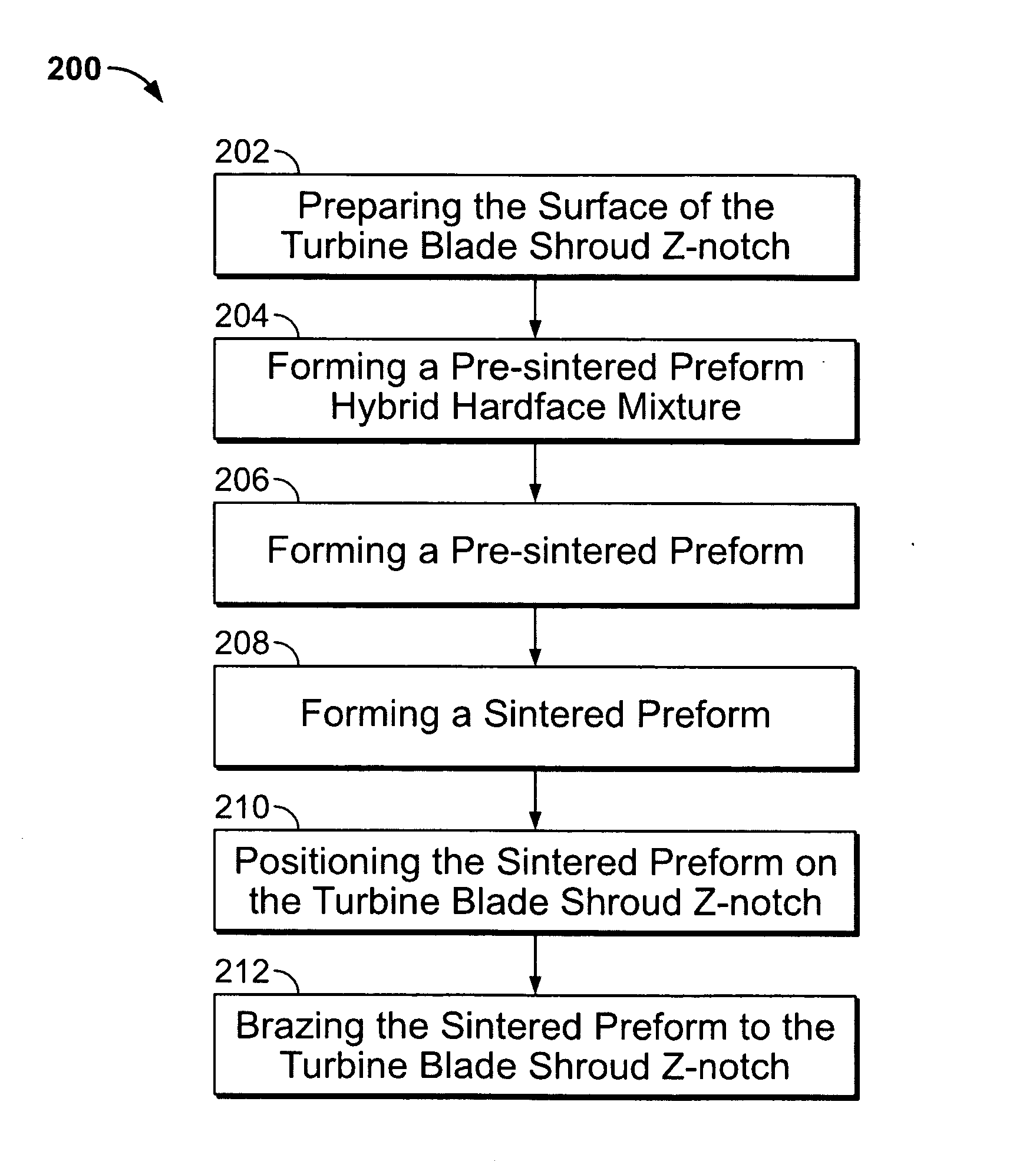
Active Publication Date: 2007-07-05
GENERAL ELECTRIC CO
View PDF13 Cites 47 Cited by
  • Summary
  • Abstract
  • Description
  • Claims
  • Application Information

AI Technical Summary

Problems solved by technology

For example, during operation of the engine there may be minute, but continuous, vibration of adjacent blades with respect to each other and the hub.
Since the vibration in the blades is mitigated by the close tolerances of the shroud's Z-notches, this condition may increase wear in the vicinity of the shroud's Z-notches as the adjacent notches rub against each other.
In general, shroud materials do not have the hardness characteristics to withstand the long-term cumulative effects of contact and rubbing.
The surface materials of the notches tend to wear.
As the notches wear, the effects of the aforementioned twisting and vibration will increase and maintenance shutdowns and repairs may be more frequent.
In general, spray methods may not offer the long-term results achieved by some welding and brazing methods.
This situation tends to increase the number and the length of post-weld inspections and weld remediation activities.
For example, welding defects typically include weld cracking, porous hardface layers, poor hardface bonding and adhesion, oxidizing of the hardface material and the substrate, and cracking of the substrate due to the creation of a heat affected zone.

Method used


Image

  • Machine components and methods of fabricating and repairing
  • Machine components and methods of fabricating and repairing
  • Machine components and methods of fabricating and repairing

Examples


Embodiment Construction

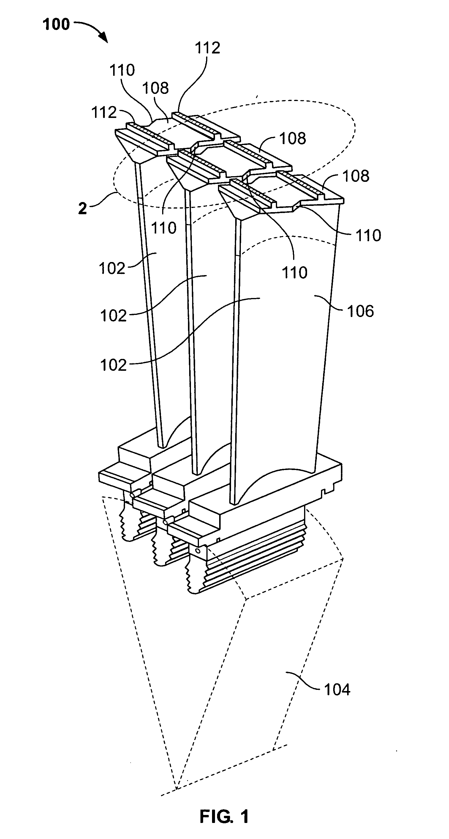
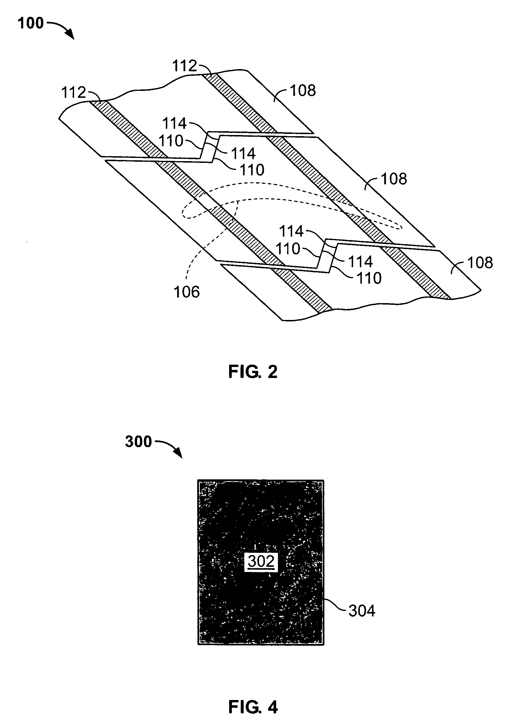
[0016]FIG. 1 is a side perspective view of a section of an exemplary combustion turbine engine 100. Engine 100 has a plurality of turbine blades 102 coupled to a hub 104. In the exemplary embodiment, blades 102 are third stage buckets. Hub 104 is coupled to a turbine shaft (not shown in FIG. 1). Each of blades 102 have a corresponding airfoil 106 and a corresponding turbine blade shroud 108 fixedly coupled to airfoil 106 at the radially outermost extremity of airfoil 106. Each shroud 108 has two correspondingly opposite Z-notches 110 with only one for each shroud 108 illustrated. Protrusions 112 facilitate coupling a substantially arcuate seal ring (not shown in FIG. 1) to shrouds 112 to facilitate mitigation of blade 102 circumferential movement and vibration. The portion of FIG. 1 enclosed by the bold dotted line and labeled 2 is illustrated in FIG. 2.

[0017] In one embodiment, engine 100 is a MS9001FA engine, sometimes referred to as a 9FA engine, commercially available from Gene...


PUM

PropertyMeasurementUnit
thicknessaaaaaaaaaa
thicknessaaaaaaaaaa
porosityaaaaaaaaaa

Abstract

A method of fabricating a machine component is provided. The method includes preparing at least a portion of a surface of a machine component for receiving a sintered preform. The method also includes forming a pre-sintered preform hybrid hardface mixture that includes combining a predetermined portion of at least one hardfacing material with a predetermined portion of at least one brazing material. The method further includes forming a pre-sintered preform. The pre-sintered preform has predetermined dimensions. The method also includes forming the sintered preform and positioning the sintered preform on the machine component. The method further includes fixedly coupling the sintered preform to at least a portion of the machine component via brazing.

Description

BACKGROUND OF THE INVENTION [0001] This invention relates generally to fabricating machine components and more particularly, to methods and apparatus for forming a hardfacing layer on a machine component. [0002] Most known turbine blades are coupled to a central hub that is attached to a driven shaft and the blades are substantially radially disposed with respect to the axis of the hub and shaft. The blades include an airfoil and a high energy, driving fluid impacts the airfoils and imparts a rotational energy that in turn rotates the shaft. Some known combustion turbine blades have shrouds at the outer extremities of the associated airfoils. The blade shrouds are nested in close proximity to each other. Many known turbine blade shrouds have a mechanical interlocking feature in the form of a notch, often referred to a “Z-notch” due to its shape closely resembling the letter Z, that allows each blade to be physically interlocked at its shroud with an adjacent blade. [0003] There are ...

Claims


Application Information

Patent Timeline
Patent Type & Authority Applications(United States)
IPC IPC(8): B22F7/00
CPCB23K1/0018B23K2201/001B23P6/005F01D5/005Y10T428/12861F05D2230/22B22F7/062B22F5/04F01D5/225B23K2101/001B23K1/00B22F3/02
Inventor SATHIAN, SUJITHKURUVILLA, ANJILIVELIL K.NOWAK, DANIEL
Owner GENERAL ELECTRIC CO
Why Eureka
Try Eureka