Polishing pad and method for manufacturing the polishing pad

a technology of polishing pads and polishing particles, which is applied in the direction of cleaning equipment, synthetic resin layered products, weaving, etc., can solve the problems of inability to effectively remove debris from the workpiece being polished, inability to smoothly flow slurry, and inability to efficiently distribute polishing particles in slurry, so as to eliminate the difference between batches of polishing pads made according to conventional methods

Inactive Publication Date: 2007-07-05
SAN FANG CHEM IND
View PDF78 Cites 5 Cited by
  • Summary
  • Abstract
  • Description
  • Claims
  • Application Information

AI Technical Summary

Benefits of technology

[0009] An advantage of the method according to the present invention is that the properties, content, particle content and modulus of the polymer can be adjusted in order to control the hardness and compressibility of the polishing pad.
[0010] Another advantage of the method according to the present invention is that the fibers of the non-woven cloth and the holes of the continuous porous polymer enable slurry to flow smoothly.
[0011] Another advantage of the method according to the present invention is that where the fibers are made of more than two materials, the rigidity of the polishing pad can be adjusted through adjusting the rigidity and hydrophilicity of the fibers. The rigidity and hydrophilicity of the fibers can be adjusted through adjusting the content of the fibers.
[0012] An advantage of the method according to the present invention is that debris is expelled by the fibers exposed from the polymer resin. Thus, the workpiece is not vulnerable to scratches. This is particularly important in the polishing of electro-optic elements or semiconductors.
[0013] An advantage of the method according to the present invention is that the polishing pad can be made in a roll-to-roll manner according to the method of the present invention, i.e., it can be made in a roll suitable for mass production. Thus, with the method of the present invention, differences between batches of polishing pads made according to conventional methods are eliminated. That is, polishing pads made according to the method of the present invention provide similar polishing effects.

Problems solved by technology

However, as the density of the thermosetting plastic varies at different points in the mold, and as the temperature varies at different points in the mold, the resultant polishing pads includes holes that are different from one another in size and unevenly positioned.
Moreover, the holes are often not communicated with one another so that slurry cannot flow smoothly and that polishing particles contained in the slurry cannot be distributed effectively.
Furthermore, debris cannot be expelled from a workpiece that is being polished so that the debris stays on and scratches the workpiece.
Thus, it is very difficult to control the polishing effects using the polishing pads made in this conventional process.

Method used


Image

  • Polishing pad and method for manufacturing the polishing pad
  • Polishing pad and method for manufacturing the polishing pad
  • Polishing pad and method for manufacturing the polishing pad

Examples


Embodiment Construction

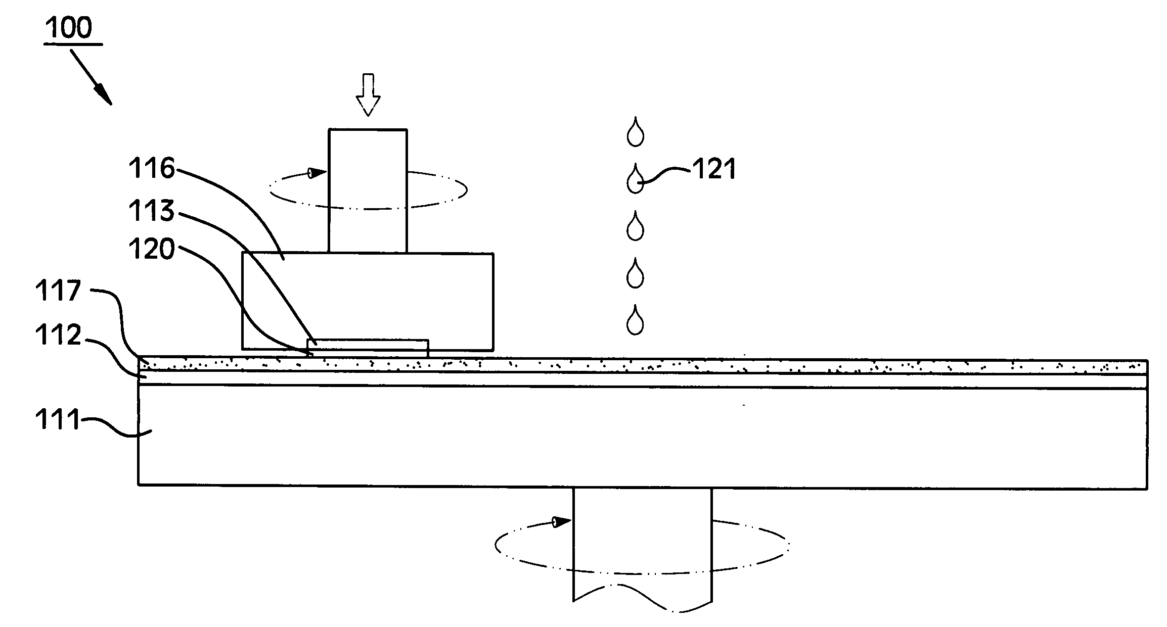
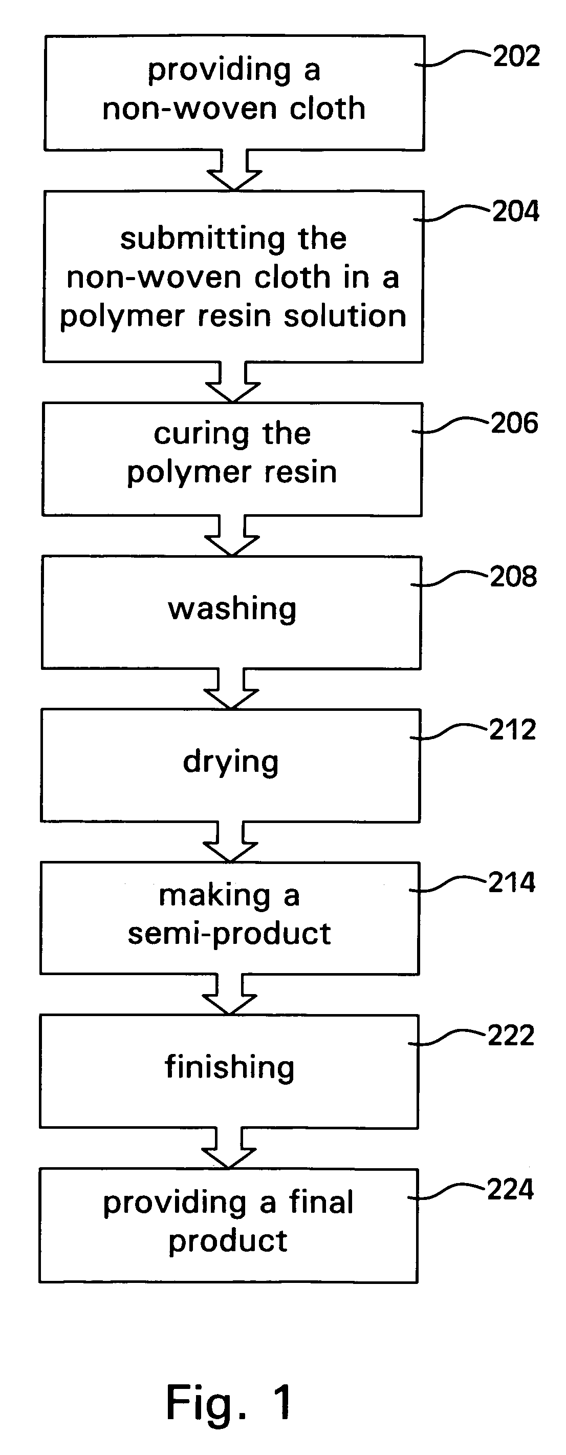
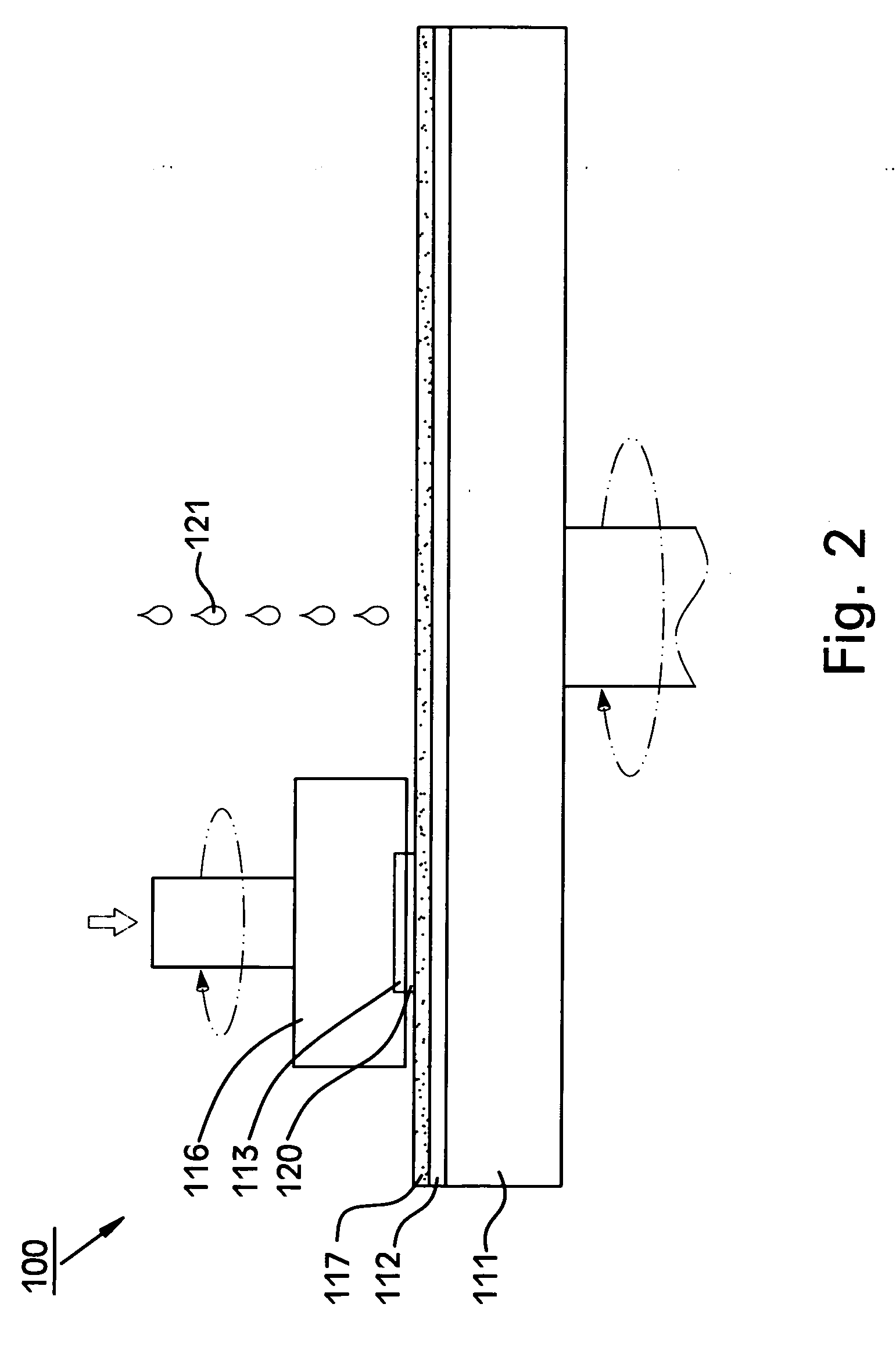
[0018] Referring to FIG. 1, there is shown a method for manufacturing a polishing pad according to the preferred embodiment of the present invention.

[0019] At step 202, a non-woven cloth is provided. The non-woven cloth is made of a plurality of fibers by stitching. The fibers may be single-component fibers or composite fibers. The single-component fibers may be made of polyamide resin, polyester resin, poly-acrylic resin or polyacrylonitrile resin. The composite fibers may be made of any combination of polyamide resin, polyester resin, poly-acrylic resin or polyacrylonitrile resin. In the preferred embodiment, the non-woven cloth is made of composite fibers of 3 denier by needle punch. The composite fibers include 70% of nylon and 30% of polyethylene terepthalate (“PET”). The thickness of the non-woven cloth is 2.25 mm, the density is 0.22 g / cm3, and the length-specific weight is 496 g / m2.

[0020] As step 204, the non-woven cloth is submerged in a polymer resin solution. Thus, the ...


PUM

PropertyMeasurementUnit
diametersaaaaaaaaaa
diametersaaaaaaaaaa
densityaaaaaaaaaa

Abstract

A polishing pad includes a non-woven cloth and a continuous porous polymer. The non-woven cloth includes fibers. The polymer includes a plurality of holes communicated with one another. The polymer is cured in and bonded to the non-woven cloth. A surface of the polishing pad is constituted by the fibers of the non-woven cloth and the polymer.

Description

BACKGROUND OF INVENTION [0001] 1. Field of Invention [0002] The present invention relates to a polishing pad and a method for manufacturing the polishing pad. [0003] 2. Related Prior Art [0004] Chemical mechanical polishing (“CMP”) processes are used in semi-conductors and liquid crystal display industries in order to manufacture the surfaces of semi-conductor substrates and glass substrates planar. [0005] In U.S. Pat. No. 6,860,802, “Polishing pads for chemical mechanical planarization”, for example, a thermosetting mixture is poured into a cylindrical mold with grooves. Then, the thermosetting mixture is cured and become a block. The block is cut into films. Each of the films is polished and becomes a polishing pad. However, as the density of the thermosetting plastic varies at different points in the mold, and as the temperature varies at different points in the mold, the resultant polishing pads includes holes that are different from one another in size and unevenly positioned. ...

Claims


Application Information

Patent Timeline
Patent Type & Authority Applications(United States)
IPC IPC(8): B32B27/04
CPCB32B5/18B32B2432/00B32B5/022B32B5/08B32B5/20B32B2262/0246B32B2262/0261B32B2262/0276B32B2262/0284B32B2262/12B32B2266/0242B32B2266/0257B32B2266/0264B32B2266/0271B32B2266/0278B32B2266/0285B32B2266/06B32B5/24Y10T442/2361Y10T442/241Y10T442/273Y10T442/2861Y10T442/2893
Inventor FENG, CHUNG-CHINGCHAO, CHEN-HSIANGYAO, I-PENGHUNG, YUNG-CHANGLEE, JYH-JEN
Owner SAN FANG CHEM IND
Why Eureka
Try Eureka