Laser irradiation apparatus and laser irradiation method

Inactive Publication Date: 2007-07-12
SEMICON ENERGY LAB CO LTD
View PDF8 Cites 50 Cited by
  • Summary
  • Abstract
  • Description
  • Claims
  • Application Information

AI Technical Summary

Benefits of technology

[0033] According to the present invention, it is possible to provide a laser process apparatus which can form a semiconductor f

Problems solved by technology

In such a case, it is apparent

Method used


Image

  • Laser irradiation apparatus and laser irradiation method
  • Laser irradiation apparatus and laser irradiation method
  • Laser irradiation apparatus and laser irradiation method

Examples


embodiment mode 1

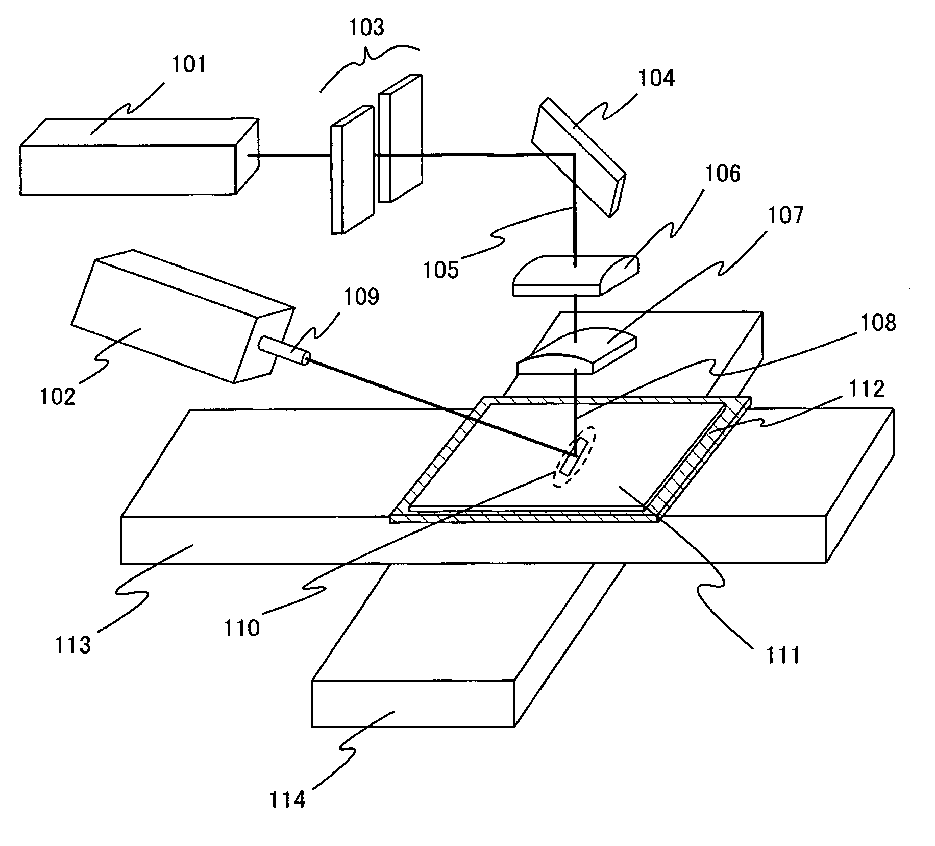
[0056] This embodiment mode is described with reference to FIG. 1 and FIGS. 3A to 3F. According to the present invention, when laser annealing is conducted to a semiconductor film with a CW linear laser beam of a harmonic, opposite end portions of the CW linear beam are blocked by a slit. At the same time, a CW laser beam of the fundamental wave is delivered so that the laser beams of the harmonic and the fundamental wave overlap with each other on an irradiation surface.

[0057] Laser oscillators 101 and 102 are known CW laser oscillators. For example, a laser whose medium is a single-crystal YAG, YVO4, YLF, YAlO3, or GdVO4, or a poly-crystal YAG, Y2O3, YVO4, YAlO3, or GdVO4, each of which is added with one or plural elements selected from the group consisting of Nd, Yb, Cr, Ti, Ho, Er, Tm, and Ta as dopant can be used. Moreover, another solid-state laser such as an alexandrite laser or a Ti: sapphire laser or a semiconductor laser such as a GaN laser, a GaAs laser, or an IsAs laser...

embodiment 1

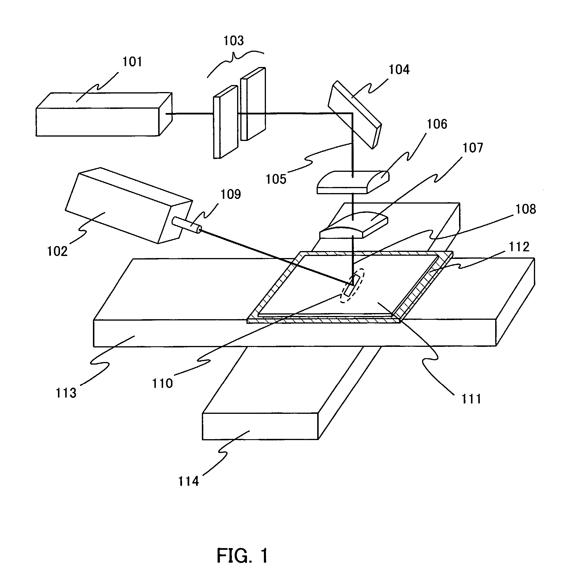
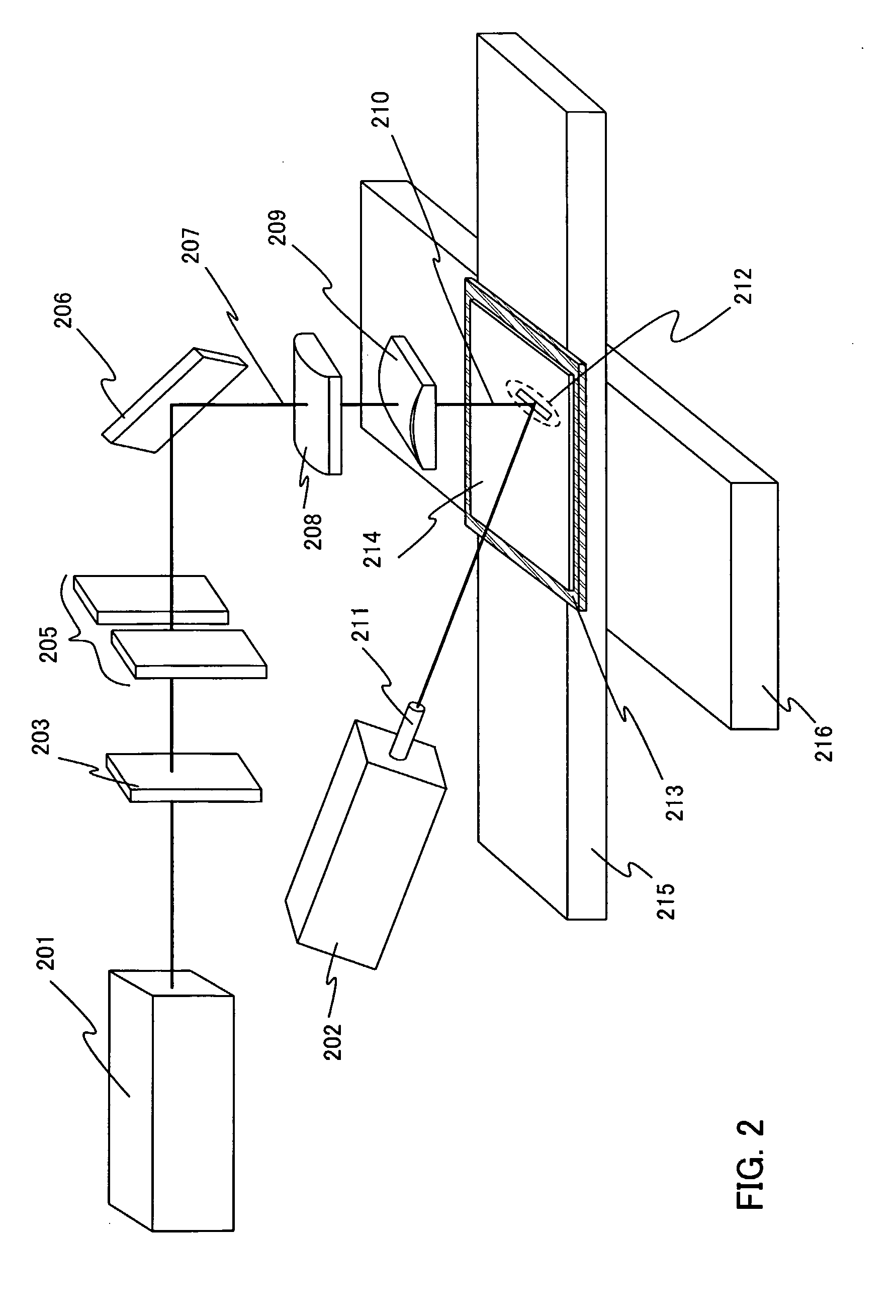
[0071] In this embodiment, a diffractive optical element (also referred to as diffractive optics or a diffractive optics element) is used to crystallize a semiconductor film more homogeneously. A harmonic of a CW laser beam is shaped into a linear or rectangular laser beam having homogeneous energy distribution with the use of the diffractive optical element, opposite end portions of this laser beam are blocked by a slit, and then the laser beam is delivered to a semiconductor film. In addition, a CW laser beam of the fundamental wave is delivered simultaneously so as to overlap the linear or rectangular beam on an irradiation surface.

[0072] A laser irradiation apparatus shown in this embodiment comprises laser oscillators 201 and 202, a diffractive optical element 203, a slit 205, a mirror 206, condensing lenses 208 and 209, a suction stage 213, an X-stage 215, and a Y-stage 216.

[0073]FIG. 2 shows an example of the laser irradiation apparatus. First, a substrate 214 over which an...

embodiment 2

[0092] In this embodiment, laser beams emitted from two CW laser oscillators of a harmonic are divided and the laser beams with different energy distribution are overlapped with each other so that a laser beam having homogeneous energy distribution is formed. Moreover, after further homogenizing the energy distribution of the laser beam by blocking end portions of the laser beam with the use of a slit, the laser beam is delivered to a semiconductor film. At the same time, a CW laser beam of the fundamental wave is delivered so as to overlap the laser beam of the harmonic on an irradiation surface. This summary is described with reference to FIG. 5 and FIGS. 6A to 6C.

[0093] Reference numerals 501 and 502 denote laser oscillators. The laser oscillators 501 and 502 are known CW laser oscillators such as a laser having a medium of a single-crystal YAG, YVO4, YLF, YAlO3, or GdVO4, or a poly-crystal YAG, Y2O3, YVO4, YAlO3, or GdVO4, each of which is added with one or plural elements sele...


PUM

PropertyMeasurementUnit
Frequencyaaaaaaaaaa

Abstract

It is an object of the present invention to provide a laser irradiation apparatus and a laser irradiation method for conducting a laser process homogeneously to the whole surface of a semiconductor film. A first laser beam emitted from a first laser oscillator passes through a slit and a condensing lens and then enters an irradiation surface. At the same time, a second laser beam emitted from a second laser oscillator is delivered so as to overlap the first laser beam on the irradiation surface. Further, the laser beams are scanned relative to the irradiation surface to anneal the irradiation surface homogeneously.

Description

TECHNICAL FIELD [0001] The present invention relates to a laser irradiation apparatus (an apparatus including a laser and an optical system for guiding a laser beam emitted from the laser to an irradiation object) and a laser irradiation method which conduct annealing, for example, for a semiconductor material homogeneously and effectively. Further, the present invention relates to a method for manufacturing a semiconductor device by applying the laser process. BACKGROUND ART [0002] In recent years, a technique for manufacturing a thin film transistor (hereinafter referred to as a TFT) over a substrate has made a great progress, and application to an active matrix display device has been advanced. In particular, a TFT formed using a poly-crystalline semiconductor film is superior in field-effect mobility (also referred to as mobility simply) to a TFT formed using a conventional amorphous semiconductor film, and therefore high-speed operation has become possible. For this reason, it ...

Claims


Application Information

Patent Timeline
IPC IPC(8): B23K26/08B23K26/06H01L21/268H01L21/20
CPCB23K26/0604B23K26/0656H01L21/2026H01L27/1285H01L27/1266H01L27/13H01L21/268B23K26/066H01L21/02425H01L21/02683H01L21/02686H01L21/02488H01L21/02422H01L21/02532H01L21/0242H01L21/02672H01L21/02691H01L21/0268
Inventor TANAKA, KOICHIROYAMAMOTO, YOSHIAKIOMATA, TAKATSUGU
Owner SEMICON ENERGY LAB CO LTD
Why Eureka
Try Eureka