Ventilator Device For Dehumidification

a technology of dehumidification and ventilator, which is applied in the direction of heating types, instruments, domestic cooling apparatus, etc., can solve the problems of humidity and excess moisture or condensation, damage to contents and the structure itself, and damage to the structure, so as to reduce the humidity in the structure, reduce the humidity, and remove the stalest and dampest air

Inactive Publication Date: 2007-07-12
AIR TECH EQUIP
View PDF10 Cites 5 Cited by
  • Summary
  • Abstract
  • Description
  • Claims
  • Application Information

AI Technical Summary

Benefits of technology

[0010] The interior air withdrawn from the structure is exhausted outside into the atmosphere, removing the stalest and dampest air. Normally external ambient air is drier (lower relative humidity) than moisture laden interior air. The present system forces air circulation of drier outside air into the structure while exhausing moist interior air, and thereby reduces humidity in the structure for humidity control. Nonetheless, even where there is high exterior humidity, continuous circulation of air in the structure is desirable to minimize condensation.

Problems solved by technology

Furthermore, normal usage of these structures (garages, sheds, greenhouses, pool houses) enhances and naturally creates humidity issues.
. . ) creating excess humidity which can damage contents and the structure itself if not resolved.
These structures are often open in the daytime for use and closed overnight, which lets in humidity in the daytime and traps it in overnight causing humidity and excess moisture or condensation issues.
Summertime movement or infiltration of air from outside can result in condensation, which can lead to mold formation and odors, as well as structural damage and rust formation on tools and equipment.
Current household ventilation systems do not address the issues of these auxiliary structures in view of the risk of air contamination into living areas.
De-humidifiers with condensate coils address localized indoor humidity problems, however they are very costly to operate and do not address indoor air quality.

Method used


Image

  • Ventilator Device For Dehumidification
  • Ventilator Device For Dehumidification
  • Ventilator Device For Dehumidification

Examples


Embodiment Construction

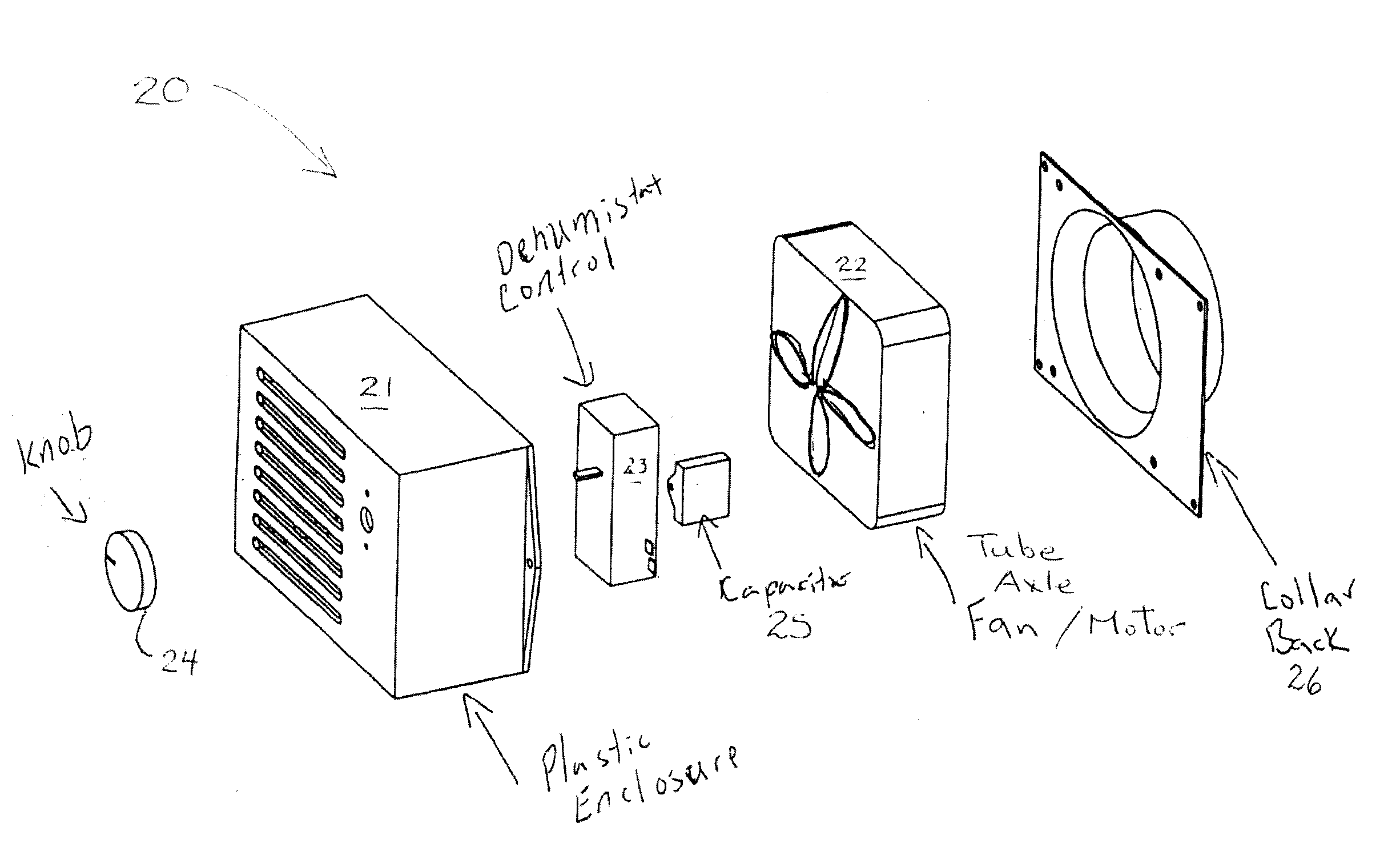
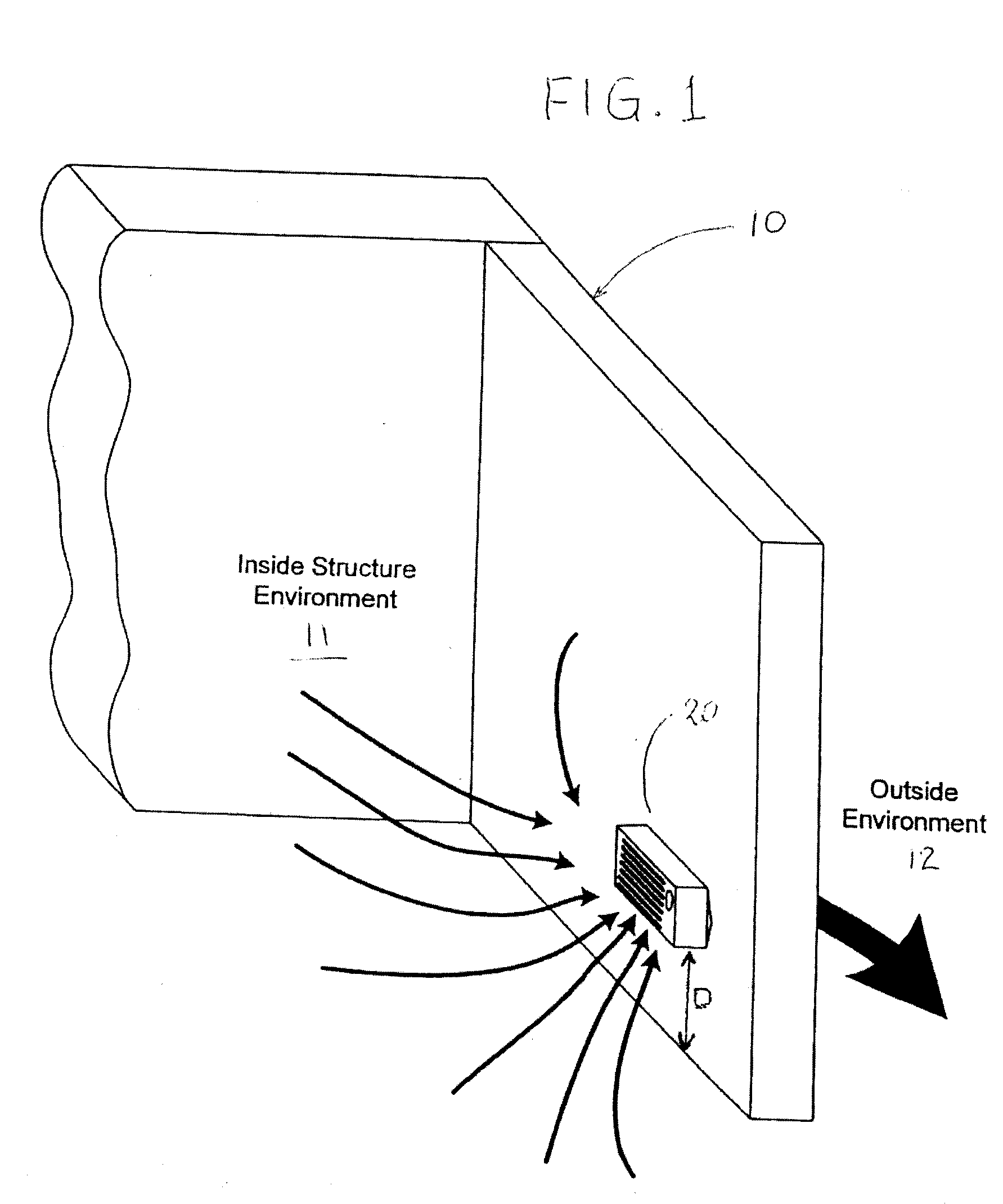
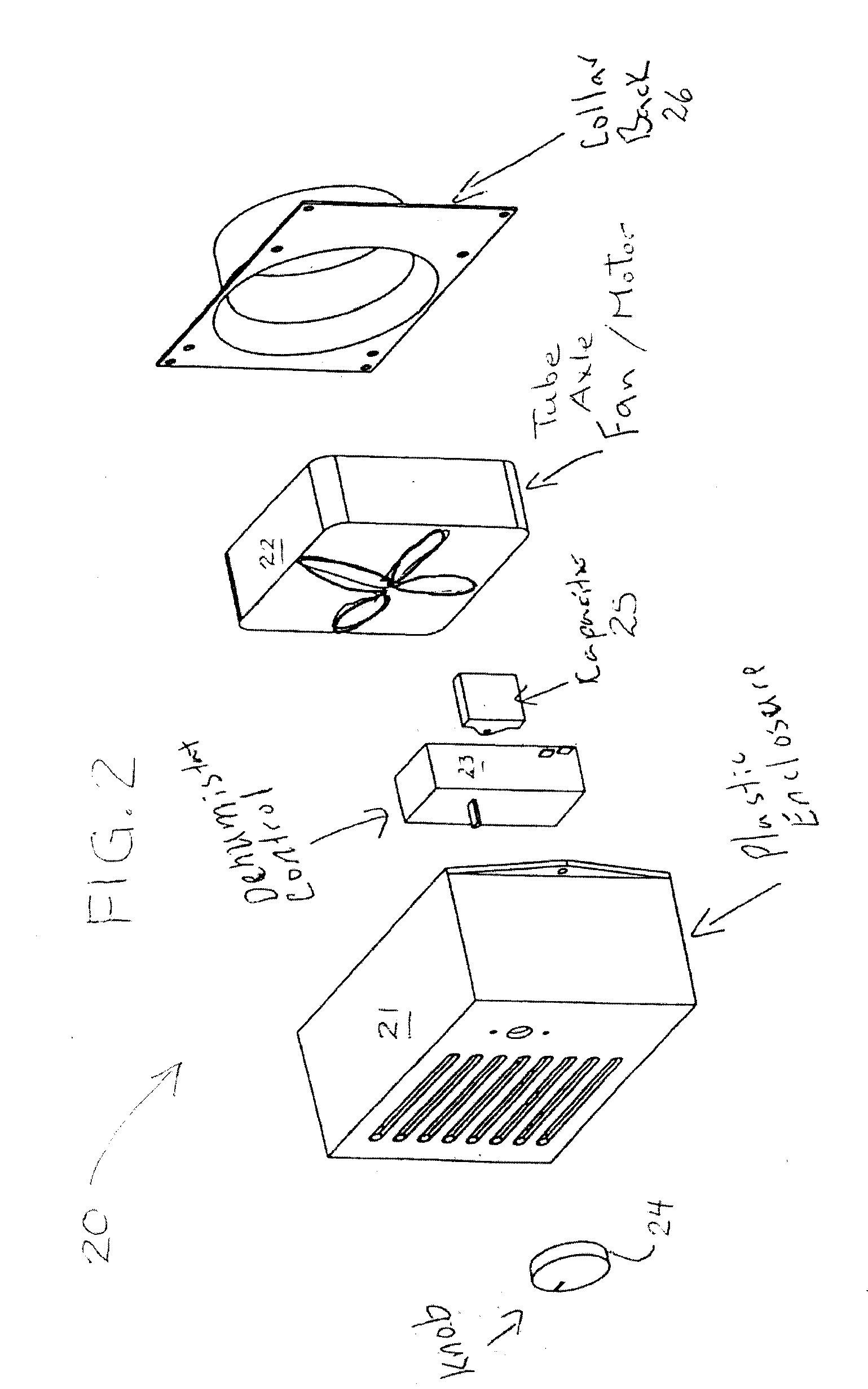
[0015] As may be seen from FIG. 1, an enclosed structure, such as a garage, pool shed or similar annex or out building, is represented, in part, by wall structure 10. The ventilation and dehumidification device is generally indicated at 20, located a distance D above the floor of the structure. Although the distance D is not fixed, it is preferable to be in proximity to the floor.

[0016] It is to be understood that the present device may be located at any height on an exterior wall of a structure. However, the device works more efficiently in general proximity to the floor level of the structure where accumulated moisture will collect, and where cooler damp air is present. Warmer air, at higher points within the structure, will then be drawn downwardly to replace exhausted air, thereby interacting with floor level moisture, and absorbing same prior to being exhausted. As the device is located higher from the floor of the structure, its efficiency is reduced, but it will still remove...


PUM


Abstract

A ventilation device and the method of use thereof for dehumidification of residential attached or detached garages, sheds, greenhouses, RVs, motorhomes and other similar structures. This device and method uses an extraction ventilator to dry out the structure's environment, and reduce the interior humidity using a motorized fan to expel moisture latent air out of the structure. The fan continuously runs at minimal speeds to continuously exhaust interior air and ventilate the structure, thereby controlling the garage environment, while eliminating backdrafts, and preventing animals, snow and rain from entering the structure. The device uses a dehumidistat control to activate the fan to maximum ventilation capacity when the humidity reaches the set point, exhausting ambient air and extracting excess humidity from the structure. Once the humidity drops below the set point, the dehumidistat deactivates and returns the ventilator to minimum speed operator.

Description

TECHNICAL FIELD [0001] The present invention relates to a humidity control device and to controlled humidity transfer during ventilation of a structure. BACKGROUND OF THE INVENTION [0002] New and better construction methods and materials have resulted in more air tight construction, to the point where ventilation has become a necessity for humidity control in annex structures such as newer built or newly renovated garages, pool or garden structures or in similar structures. [0003] Furthermore, normal usage of these structures (garages, sheds, greenhouses, pool houses) enhances and naturally creates humidity issues. Introduction of wet and humid equipment to these structures is common (snowblowers in winter, cars anytime of the year, pool houses in general, sprinklers in greenhouses in hot days makes them to hot and humid for plants . . . ) creating excess humidity which can damage contents and the structure itself if not resolved. [0004] These structures are often open in the daytim...

Claims


Application Information

Patent Timeline
Patent Type & Authority Applications(United States)
IPC IPC(8): F24F3/14F25D17/04
CPCF24F11/0015Y02B30/746F24F11/0079F24F11/30F24F2110/20F24F11/77Y02B30/70
Inventor BOUDREAU, PATRICKLESTAGE, MARC
Owner AIR TECH EQUIP
Why Eureka
Try Eureka