Energy storage system for electric or hybrid vehicle

a technology of energy storage and electric or hybrid vehicles, applied in the direction of battery/fuel cell control arrangement, dynamo-electric converter control, electric devices, etc., can solve the problems of reducing the efficiency of switching devices in the power control circuit, affecting the operation of the vehicle, and the known energy storage system is less effective at providing relatively high power levels

Active Publication Date: 2007-07-12
GENERAL ELECTRIC CO
View PDF58 Cites 117 Cited by
  • Summary
  • Abstract
  • Description
  • Claims
  • Application Information

AI Technical Summary

Benefits of technology

[0007] In one aspect, a battery load leveling system for an electrically powered system in which a battery is subject to intermittent high current loading is provided. The system includes a first battery, a second battery, and a load coupled to the batteries. The system also includes a passive storage device, a unidirectional conducting apparatus coupled in series electrical circuit with the passive storage device and poled to conduct current from the passive storage device to the load, the series electrical circuit coupled in parallel with the battery such that the passive storage device provides current to the load when the battery terminal voltage is less than voltage on the passive storage device, and a battery switching circuit that connects the first and second batteries in either a lower voltage parallel arrangement or a higher voltage series arrangement.
[0008] In another aspect, an electric vehicle is provided. The electric vehicle includes a first battery, a second battery, a load coupled to the first and second batteries; the first and second batteries configured to provide the propulsive force for moving the vehicle, and a battery load leveling system. The battery load leveling system includes a passive storage device, a unidirectional conducting apparatus coupled in series electrical circuit with the passive storage device and poled to conduct current from the passive storage device to the load, the series electrical circui

Problems solved by technology

Such voltage reduction can interfere with proper operation of the vehicle or reduce efficiency of the switching devices in the power control circuit since the control circuit must also be designed to operate at high efficiency at full battery voltage, i.e., when the vehicle is drawing nominal current in a constant speed mode.
As a result, known energy storage systems are less effective for provi

Method used


Image

  • Energy storage system for electric or hybrid vehicle
  • Energy storage system for electric or hybrid vehicle
  • Energy storage system for electric or hybrid vehicle

Examples


Embodiment Construction

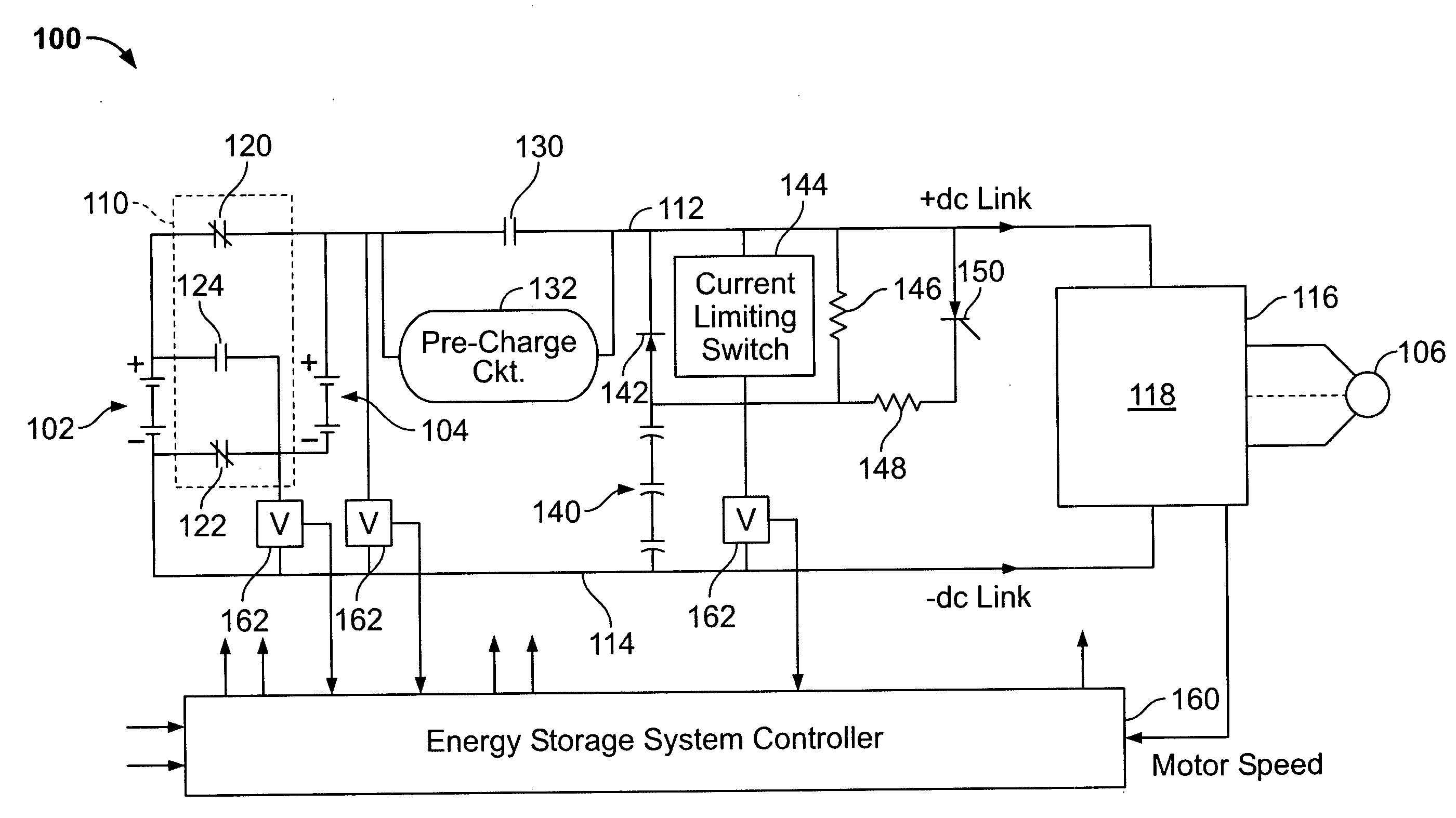
[0019]FIG. 3 illustrates a battery load leveling system 100. The battery load leveling system 100 includes a first battery 102 and a second battery 104 that are utilized to supply power to a load 106. Load 106 may be an alternating current (AC) or direct current (DC) load such as an electric traction motor for powering electric vehicles. Battery load leveling system 100 also includes a battery switching circuit 110 that includes a plurality of contactors that are operable to connect the first and second batteries 102 and 104, respectively, in either a lower voltage parallel or a higher voltage series arrangement.

[0020] Battery switching circuit 110 enables the positive and negative terminals of first battery 102 and second battery 104 to be connected to respective ones of a positive bus 112 and negative bus 114. Positive and negative buses 112 and 114, also referred to herein as the positive and negative DC links, couple batteries 102 and 104 to a power electronics circuit 116 whic...


PUM


Abstract

A battery load leveling system for an electrically powered system in which a battery is subject to intermittent high current loading, the system including a first battery, a second battery, and a load coupled to the batteries. The system includes a passive storage device, a unidirectional conducting apparatus coupled in series electrical circuit with the passive storage device and poled to conduct current from the passive storage device to the load, the series electrical circuit coupled in parallel with the battery such that the passive storage device provides current to the load when the battery terminal voltage is less than voltage on the passive storage device, and a battery switching circuit that connects the first and second batteries in either a lower voltage parallel arrangement or a higher voltage series arrangement.

Description

BACKGROUND OF THE INVENTION [0001] This invention relates generally to electric drive systems and, more particularly, to a battery load leveling system that may be utilized with a hybrid or an electric vehicle. [0002] At least one known vehicle includes batteries, typically lead-acid batteries, to provide electric power for vehicle propulsion. For example, FIG. 1 is a prior art vehicle that includes a conventional alternating current (AC) electric propulsion system 10 that is used in electric propelled and also hybrid-electric vehicles. The electric propulsion system includes at least one energy storage unit such as a lead acid battery 12, and a direct current (DC) contactor 14 to electrically disconnect the energy storage unit 12 from a traction inverter 16 via a DC link 18. Specifically, the battery 12 is connected to a DC link which connects to a frequency controlled inverter such as traction DC-AC inverter 16 for controlling power to an AC motor 20. [0003] In the operation of th...

Claims


Application Information

Patent Timeline
IPC IPC(8): H02J1/00B60L50/16
CPCB60L11/1864B60L2210/20B60R16/03H02J7/0024Y02T90/34Y02T10/7005Y02T10/7055Y02T10/7061Y02T10/725H02J7/345B60L58/21H02J2310/46Y02T10/70Y02T10/72Y02T90/40Y02T10/7072Y02T90/14
Inventor KING, ROBERT DEANRICHTER, TIMOTHY GERARDSALASOO, LEMBIT
Owner GENERAL ELECTRIC CO
Why Eureka
Try Eureka