Umts receiver symbol synchronization

a receiver and symbol technology, applied in the field of umts receiver symbol synchronization, can solve the problems of high complexity of the process, still arise, and the path characteristics vary with tim

Inactive Publication Date: 2007-07-12
ST ERICSSON SA
View PDF6 Cites 5 Cited by
  • Summary
  • Abstract
  • Description
  • Claims
  • Application Information

AI Technical Summary

Benefits of technology

[0014] An object of the present invention is to mitigate the above described problems and provide an efficient way of performing time drift compensation in a receiver and a set of dedicated resources to be implemented in the receiver to effect the time drift compensation.

Problems solved by technology

A major problem in particular is that the characteristics of the paths vary with time, due to the fact that the receiver is mobile.
These varying characteristics must be adjusted dynamically, and that is a highly complex process.
When combining the symbols by summing each path, another problem arises.
However, a problem may still arise: after the symbol of BS1 has been subject to the delay D, a BS1 symbol of order K+1 may be aligned with a BS2 symbol of order K, and not with a BS2 symbol of order K+1, which is required to produce a coherently composite symbol.
When the delay of two multi-path symbols exceeds this maximum delay, symbol alignment is no longer possible, and symbols relating to the path of BS1 will consequently be lost.
The symbol of BS1 must then be delayed by I, i.e. one symbol period, in order for the BS1 symbol of order K to become aligned with the BS2 symbol of order K. However, if the maximum delay is reached, a coherent adding of symbols can no longer be accomplished.
Two major problems arise when combination of symbols is to be undertaken.
However, the symbols derived from BS2 may disappear due to fading, which has the effect that timing control and decisions taken to omit / repeat symbols must be done in relation to a new reference path.
These problems will make the management of time-drift compensation difficult.
This has a major impact on performance loss of the receiver, since a chip is omitted instead of a complete symbol, i.e. only 1 / N out of a symbol consisting of N chips is omitted / repeated by this operation.
However, the receiver disclosed in French patent application No. 02 10452 of 21 Aug. 2002 still presents unacceptable performance losses.
Another problem is that the software management, even though it has been simplified, is still rather complex.

Method used


Image

  • Umts receiver symbol synchronization
  • Umts receiver symbol synchronization
  • Umts receiver symbol synchronization

Examples


Embodiment Construction

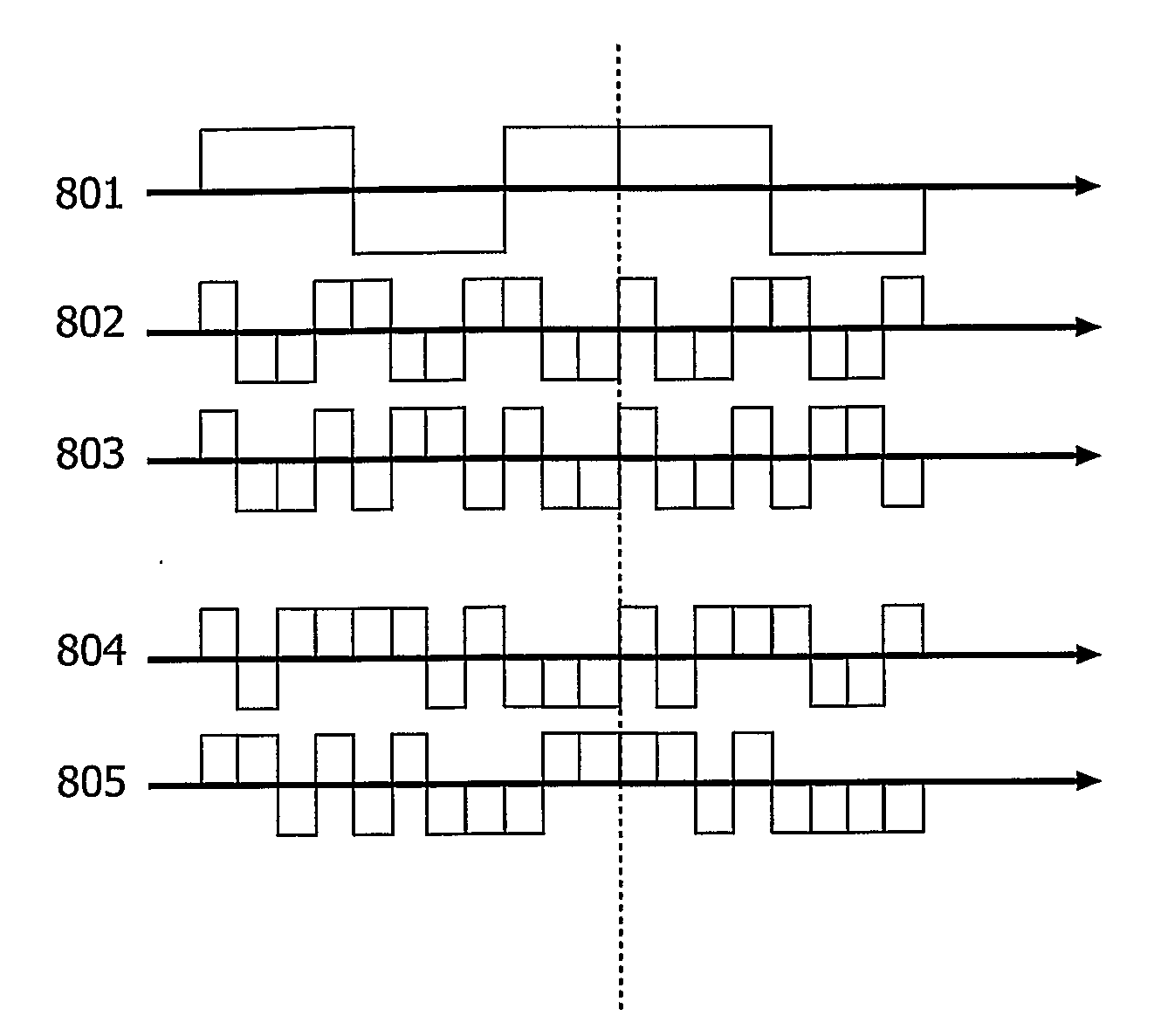
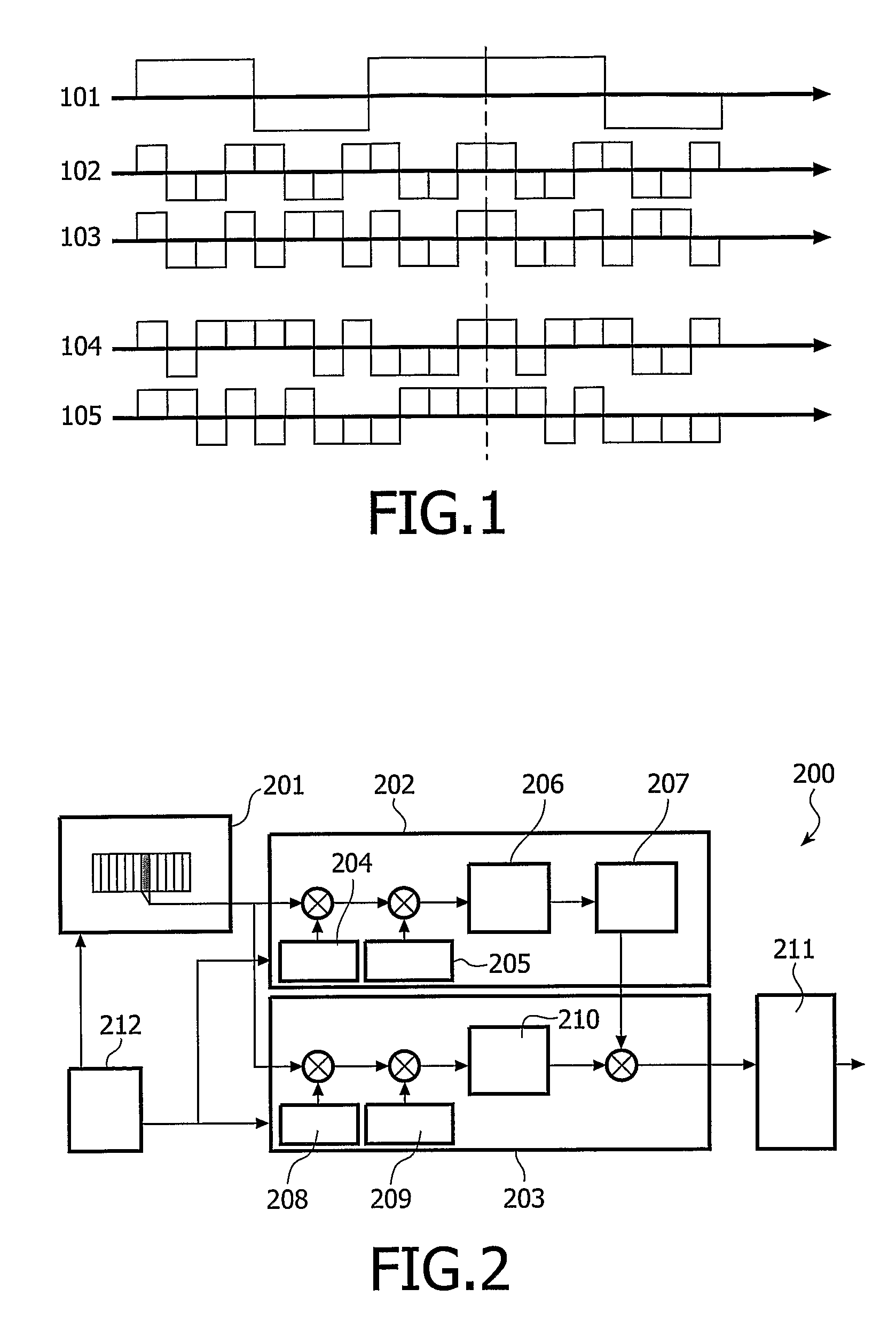
[0040] In UMTS, spreading is used at the transmitting side, i.e. at the base station, to translate each symbol into a sequence of bits. Each symbol is multiplied with a spreading code comprising N bits, or chips, per symbol. The number N of chips in the spreading code is typically known as the spreading factor (SF). The value of SF varies from 4 to 256 depending on the data channel, but in case of the pilot channel employed in the mobile phone receiver, SF is set to 256. FIG. 1 shows the spreading of five symbols 101 with a spreading code 102 having SF=4. The resulting code is shown at 103. Thereafter, each chip is modulated with a scrambling code 104 over a sequence of 38400 chips. FIG. 1 shows the first 20 chips of the scrambling sequence. The chips, after having been subject to spreading and scrambling, are shown at 105. The dotted line indicates a slot boundary.

[0041] Thus, a two-stage modulation technique is employed at the receiver. A prior art receiver is schematically shown...


PUM


Abstract

The present invention relates to a method of performing time drift compensation in a receiver (200) and a receiver (200) for performing time drift compensation. The basic idea of the invention is that a signal is received at the receiver. A control pulse is produced after a certain number of chips of the received signal has been received. A variable delay that is applied to the received signal is controlled by means of the control pulse. The resulting delayed signal is supplied to demodulation units (202, 203) in the receiver, in which delayed signal chips have been omitted or duplicated. A compensation signal is supplied to the demodulation units in the receiver, and this compensation signal indicates whether chips have been omitted or duplicated in the delayed signal. Finally, the delayed signal is demodulated such that the demodulation units consider the omission or duplication of chips in the delayed signal.

Description

FIELD OF THE INVENTION [0001] The present invention relates to a method of performing time drift compensation in a receiver and a receiver for performing time drift compensation. BACKGROUND OF THE INVENTION [0002] In UMTS (Universal Mobile Telecommunications Service) data processing, data pertaining to different propagation paths reach a mobile station at different instants of time. Moreover, said data may reach the mobile station from the same or different transmitting sources, i.e. base stations. The information transmitted in each path in the air interface is sampled, demodulated and delayed at the receiver, and then combined with the correspondingly processed information of the other paths to improve the quality of the received signals. [0003] In CDMA systems, spreading is used to translate each symbol into a sequence of bits. At the transmitter, each symbol is multiplied with a wideband spreading code. The higher the bandwidth used to transmit a signal, the lower the required s...

Claims


Application Information

Patent Timeline
Patent Type & Authority Applications(United States)
IPC IPC(8): H04B1/00H04B1/707
CPCH04B1/7085H04B1/7117H04B1/7115
Inventor ARDICHVILI, EMMANUELGANDER, MARTIAL
Owner ST ERICSSON SA
Why Eureka
Try Eureka