Sterile cover for compressible stents used in percutaneous device delivery systems

a compression stent and percutaneous device technology, applied in the field of cardiac valve disease treatment, can solve the problems of affecting the quality of life of the stent, the difficulty or inability of hand-held devices to be used, and the cost of disposable devices is typically more expensive than disposable devices, so as to prevent contamination of the stent and eliminate or minimize contact.

Inactive Publication Date: 2007-07-12
MEDTRONIC INC
View PDF101 Cites 300 Cited by
  • Summary
  • Abstract
  • Description
  • Claims
  • Application Information

AI Technical Summary

Benefits of technology

[0005] The present invention provides a sterile stent cover for use in crimping or compression operations to eliminate or minimize contact between the components of a crimping device and a stented valve that is being crimped around a balloon or other catheter component. For example, in operations that utilize a tabletop crimping tool, such as the MSI Stent Crimper Model SC100 / 150, which is commercially available from Machine Solutions, Inc. of Flagstaff, Ariz., an expanded stented valve or other type of stent can be placed within a specifically sized and shaped stent cover of the present invention. The stent cover containing the stented valve can then be positioned over the end of a catheter so that the stented valve is positioned in its desired location along the length of the catheter, such as adjacent to the area of the balloon. Alternatively, a sterile stent or stented valve may be positioned in its desired location along the length of a catheter, and then the stent cover of the present invention can be placed over the top of both the end of the catheter and the stent. In yet another alternative, an expanded stented valve may be placed inside a sterile cover at a remote location within a package that can be removed to expose at least the outer surface of the stent cover to the environment. The stent cover containing the valve can then be positioned over the end of a catheter so that the stent is positioned in its desired location on the catheter. In any of these cases, the inside surface of the sterile stent cover (i.e., the surface that will come in contact with the stented valve), should remain sterile throughout the crimping procedure in order to prevent contamination of the stented valve. This can be accomplished through the use of an end cover removably attached to one end of the stent cover and / or by placing the entire stent cover inside a sterile package, for example.
[0007] With the MSI Stent Crimper set out above, for example, the crimping tool or device includes several adjustable segments positioned around a center opening, with all of the segments being equidistant from that center opening. The center opening is preferably generally annular. To position the adjustable segments in an open configuration of the crimping tool, the segments are simultaneously moved away from the center opening to provide an opening that is large enough to accommodate the stented valve in its uncompressed condition and surrounded by the stent cover. These segments are then simultaneously drawn toward the center opening to reduce the size of the center opening while retaining the generally annular shape of the opening. The size of the stented valve should be reduced to a dimension that is sufficiently small to provide for percutaneous positioning of the valved stent. That is, the crimping tool can precisely reduce the diameter of the stent within the sterile cover to either a fixed diameter over the entire length of the stent or to a stepped diameter, as desired. Because the stent within a stent cover of the invention does not come into contact with any part of the crimping tool during this process, the stent remains sterile, even if the outer surface of the stent cover is not sterile. Thus, the crimping tool advantageously does not need to be cleaned and sterilized after each crimping operation. The stent cover also provides the advantage of keeping the liquid glutaraldehyde solution or other solutions in which tissue valves are stored or rinsed from contacting the crimper parts and causing corrosion and / or contamination of the crimper tool.
[0010] The stent cover can further include an end cover that is removably attached to the proximal end of the sheath for preventing contamination of an inner area of the sheath. This end cover can be removably attached to a flange at the proximal end of the sheath. The end cover further can further include an extending tab that extends beyond the flange in at least one location.

Problems solved by technology

However, larger valves can require significantly more force for proper compression such that a hand-held device would be difficult or impossible to use.
These tabletop crimping devices are typically more expensive than disposable devices and they typically must be disassembled, cleaned, and sterilized before and / or after each crimping procedure so that any components with which the valves come in contact will remain sterile.
This process of disassembly, cleaning, and sterilizing can be time consuming and expensive, particularly for situations that require significant disassembly of the crimping device.

Method used


Image

  • Sterile cover for compressible stents used in percutaneous device delivery systems
  • Sterile cover for compressible stents used in percutaneous device delivery systems
  • Sterile cover for compressible stents used in percutaneous device delivery systems

Examples


Embodiment Construction

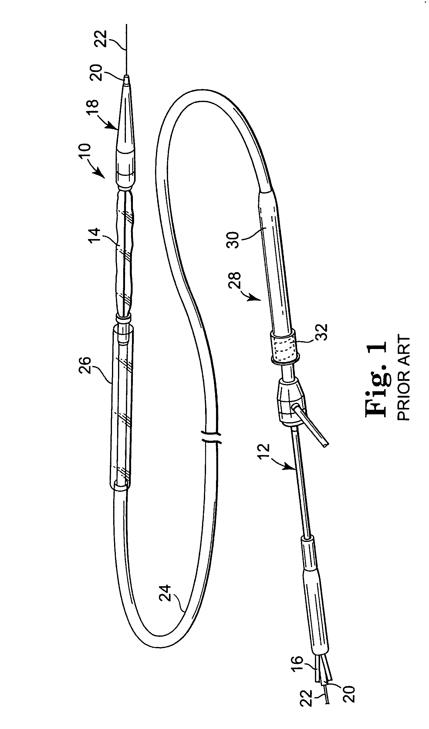
[0023] Referring now to the Figures, wherein the components are labelled with like numerals throughout the several Figures, and initially to FIG. 1, an exemplary prior art system 10 is illustrated for percutaneous insertion and implantation of a biological venous valvular replacement to a desired implant location, such as the pulmonary vein, a valved conduit or other location, for a defective or malfunctioning valve. System 10 is used for delivering a stented valve to a desired implant location, such as the pulmonary vein, a valved conduit, or other location, where such a system can be utilized with the devices and methods of the present invention. System 10 generally comprises an elongated balloon catheter 12 having an inflatable balloon 14 near the distal end of the system 10. Balloon 14 is connected for fluid communication with a lumen 16 that extends through the length of catheter 12. Lumen 16 provides for inflation and deflation of the balloon 14 with a fluid, such as a radio-o...


PUM


Abstract

A stent cover for enclosing a compressible stent during a stent crimping process, the stent cover having an outer sheath with a proximal end, a distal end, an end portion at the distal end of the sheath having a first diameter, and a stent-retaining portion adjacent to the end portion and having an uncompressed diameter that is larger than the first diameter of the end portion for retaining a stent in its uncompressed condition.

Description

TECHNICAL FIELD [0001] The invention relates generally to treatment of cardiac valve disease and more particularly to percutaneous stent and valve delivery systems. BACKGROUND OF THE INVENTION [0002] Recently, there has been increasing interest in minimally invasive and percutaneous replacement of cardiac valves. Such surgical techniques involve making a very small opening in the skin of the patient into which a valve assembly is inserted via a delivery device similar to a catheter. This technique is often preferable to more invasive forms of surgery, such as opening a large portion of the chest for cardiopulmonary bypass, for example. In the context of pulmonary valve replacement, U.S. Patent Application Publication Nos. 2003 / 0199971 A1 and 2003 / 0199963 A1, both filed by Tower, et al., describe a valved segment of bovine jugular vein, mounted within an expandable stent, for use as a replacement pulmonary valve. The replacement valve is mounted on a balloon catheter and delivered pe...

Claims


Application Information

Patent Timeline
Patent Type & Authority Applications(United States)
IPC IPC(8): A61F2/06
CPCA61F2002/9522A61F2/958A61F2/9522
Inventor RYAN, TIMOTHY R.LEMMON, JACK
Owner MEDTRONIC INC
Why Eureka
Try Eureka