Turbine platform repair using laser clad

a technology of laser cladding and turbine platform, which is applied in the direction of turbines, manufacturing tools, forging/pressing/hammering apparatus, etc., can solve the problems of other turbine engine components showing a pattern of defects

Inactive Publication Date: 2007-07-19
UNITED TECH CORP
View PDF11 Cites 15 Cited by
  • Summary
  • Abstract
  • Description
  • Claims
  • Application Information

AI Technical Summary

Benefits of technology

[0009] Accordingly, the disclosed example method and assembly provide for a prolonged life of a turbine engine component without inducing high levels of residual stress.

Problems solved by technology

The other turbine engine components exhibit a pattern of defects that occur during use of the turbine engine components.

Method used


Image

  • Turbine platform repair using laser clad
  • Turbine platform repair using laser clad
  • Turbine platform repair using laser clad

Examples


Embodiment Construction

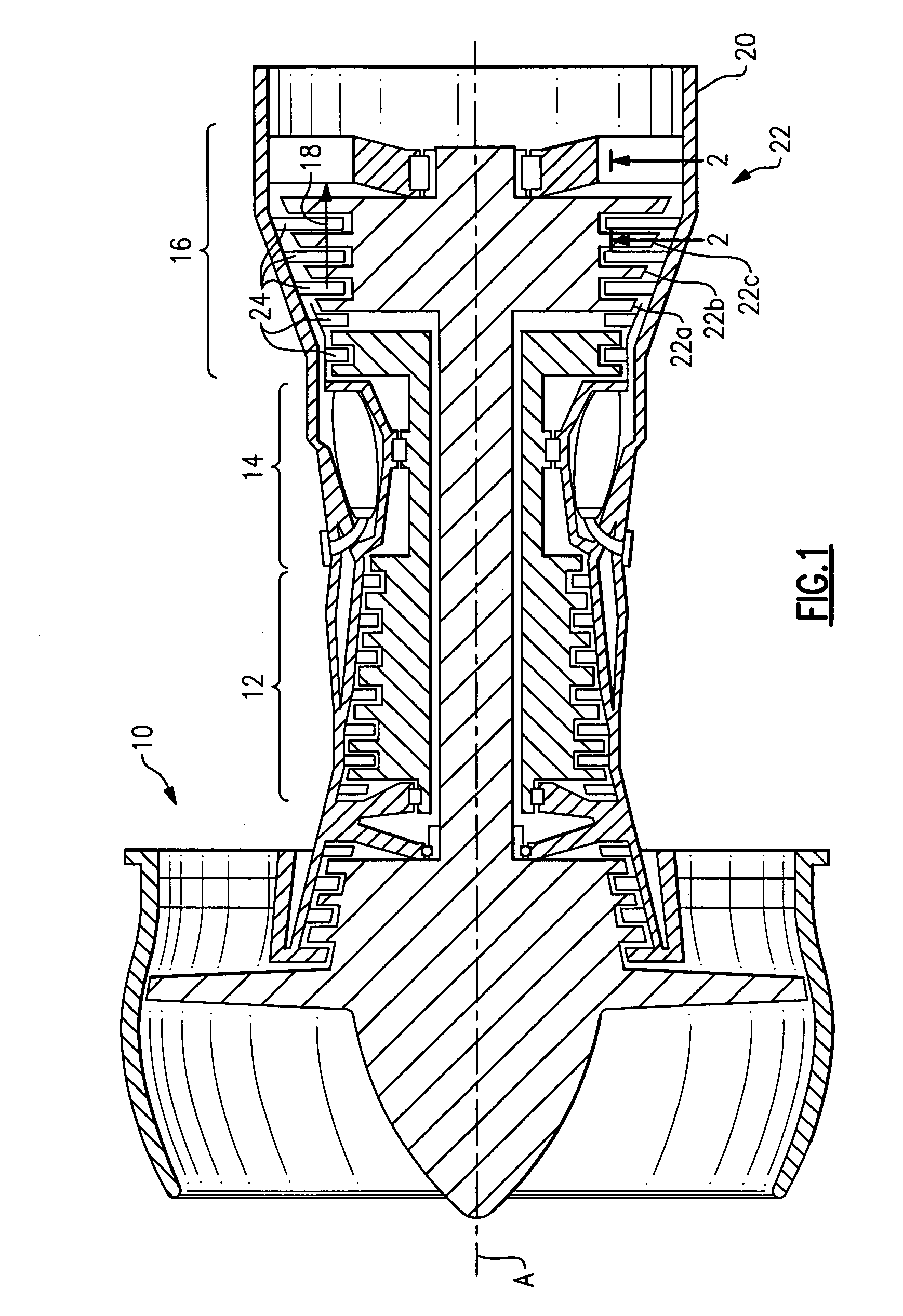
[0017]FIG. 1 illustrates selected portions of an example combustion engine 10, such as a gas turbine engine for an aircraft. In this example, the combustion engine 10 includes a compressor section 12, a combustor section 14, and a turbine section 16. The combustion engine 10 operates in a known manner, feeding compressed air or oxidizer from the compressor section 12 to the combustor section 14. The compressed air or oxidizer is mixed with fuel and reacts to produce a flow of hot gases 18. The turbine section 16 transforms the flow of hot gases 18 into mechanical energy to drive the compressor section 12. An exhaust nozzle 20 directs the hot gases 18 out of the combustion engine 10 to provide thrust to the aircraft or other vehicle.

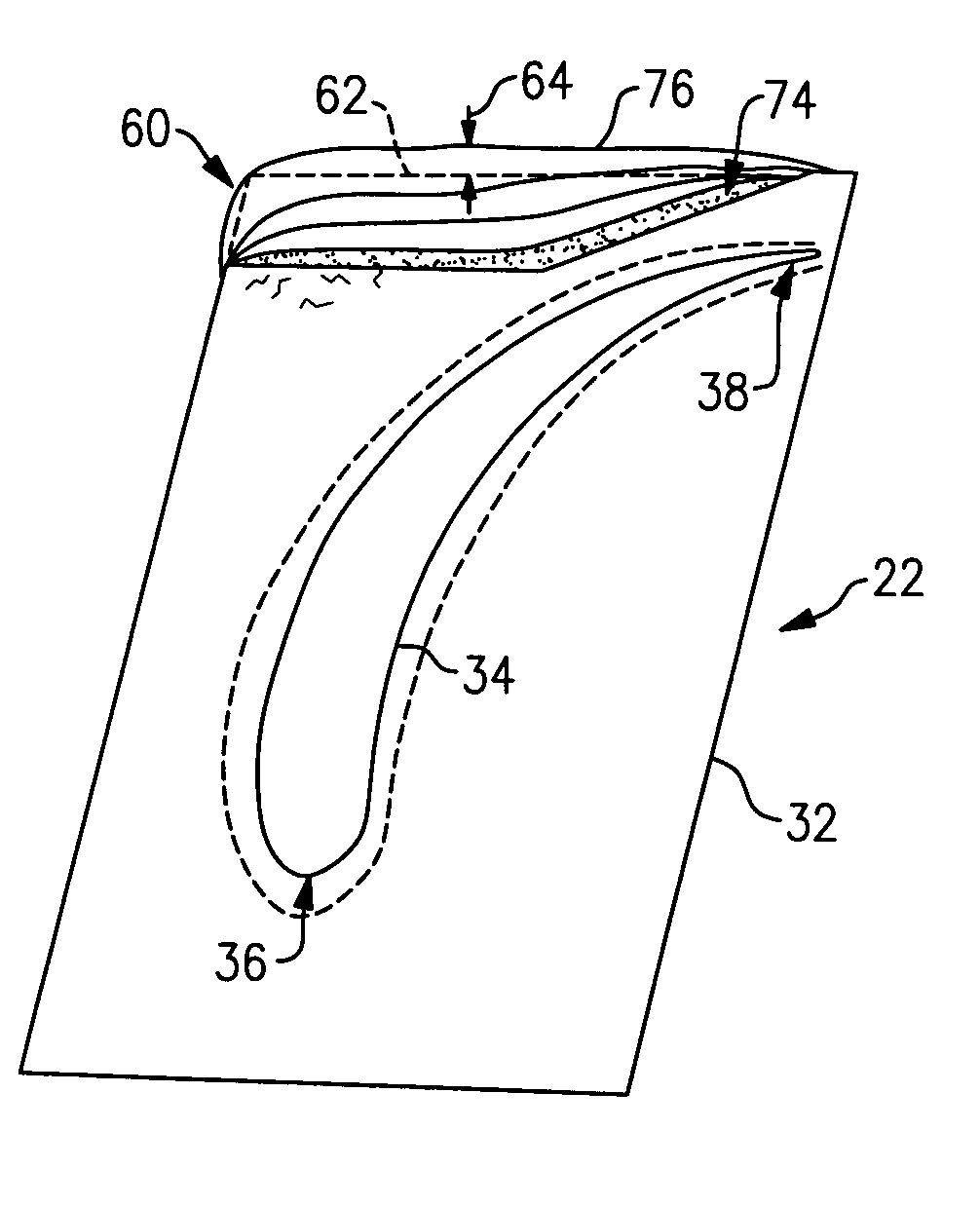
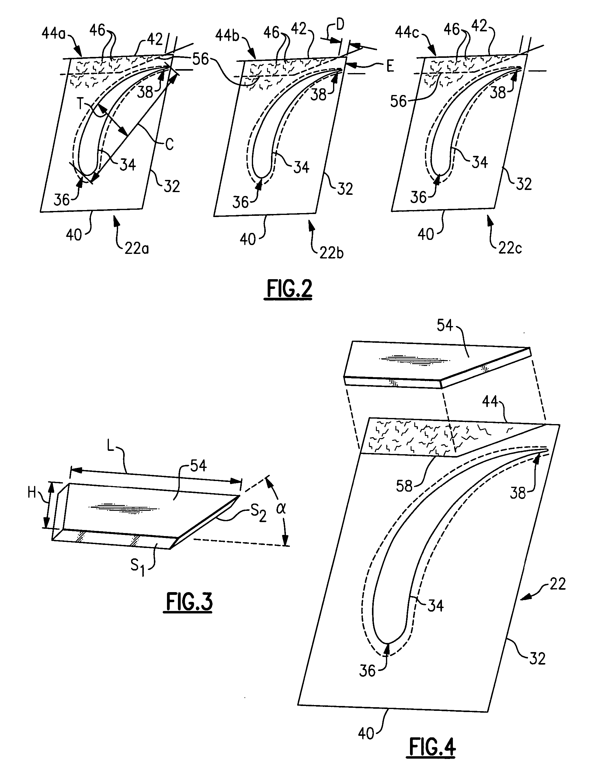
[0018] In the illustrated example, the turbine section 16 includes alternating rows of rotary airfoils or blades 22a, 22b, 22c and static airfoils or vanes 24. The vanes 24 are arranged in various stages, such a first stage, a second stage, a third stage...


PUM

PropertyMeasurementUnit
aspect ratioaaaaaaaaaa
distanceaaaaaaaaaa
lengthaaaaaaaaaa

Abstract

A method of restoring a gas turbine engine component includes removing a defect section of a turbine engine component according to a template. The template has a standardized shape and is used in a standardized location on the turbine engine component. The template is produced based upon common defect sections from other turbine engine components. A laser cladding is used to build a replacement section in place of the defect section. Thus, the turbine engine component is restored to near its original shape.

Description

RELATED APPLICATIONS [0001] This application claims priority to Singapore application number 200600246-3, filed Jan. 16, 2006. BACKGROUND OF THE INVENTION [0002] This invention relates to repair of gas turbine engine components and, more particularly, to a method for repairing a standardized section of a turbine engine component. [0003] Conventional gas turbine engines typically include turbine sections having an alternating arrangement of rotating turbine blades and static turbine vanes. A flow of hot gases from a combustor section expands against the turbine blades and vanes to rotationally drive the turbine blades, which are coupled to an engine main shaft that drives a compressor section. [0004] During engine operation, the hot gases produce a corrosive environment that corrosively attacks the surfaces of the blades and vanes and often results in corrosive pitting. The hot gases, soot from combustion, and particles within the flow of hot gases, also wear against the turbine blad...

Claims


Application Information

Patent Timeline
Patent Type & Authority Applications(United States)
IPC IPC(8): B23P15/04B23K26/21B23K26/34F02C7/00
CPCB23K2201/001B23P6/007F01D5/005F05D2240/122F05D2240/304Y10T29/4932F05D2230/30F05D2240/80F05D2230/10B23K26/3213B23K26/345Y02T50/673B23K26/32B23K26/342B23K2101/001B23K2103/18B23K2103/26Y02T50/60
Inventor CHENG, KENNYJEK, KIN KEONG THOMAS
Owner UNITED TECH CORP
Why Eureka
Try Eureka