
Highly insulated exhaust manifold

Inactive Publication Date: 2007-07-19
INTPROP HLDG
View PDF8 Cites 37 Cited by
  • Summary
  • Abstract
  • Description
  • Claims
  • Application Information

AI Technical Summary

Problems solved by technology

Unfortunately, the catalytic converter normally is mounted downstream of the exhaust manifold which conducts the heated exhaust gas from the engine.
This loss in thermal energy reduces the exhaust gas temperature before it reaches the catalytic converter and delays light off.
Cast iron exhaust manifolds are useful but heavy.
Welded tubing exhaust manifolds have less mass, but are complicated and expensive.
In addition, the metal inner layer is subject to erosion or loss of integrity over time from thermal cycling.

Method used


Image

  • Highly insulated exhaust manifold
  • Highly insulated exhaust manifold
  • Highly insulated exhaust manifold

Examples


examples

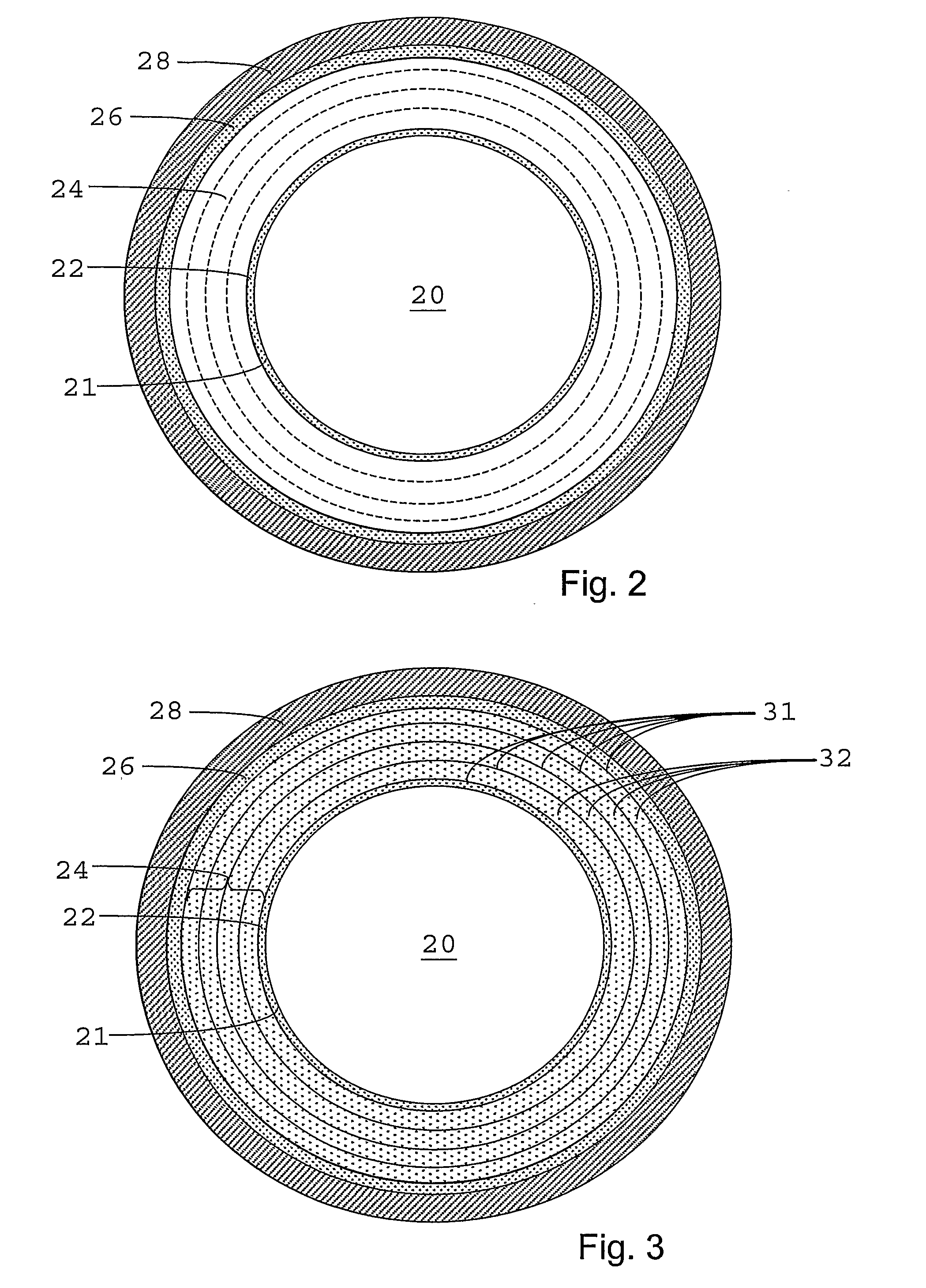
[0082] A series of 4-inch diameter disc composites were prepared in order to simulate the composite structure of an exhaust manifold having a composite insulation zone as described herein, and to demonstrate the improved insulative properties of such a composite structure. In all, four disc composites were prepared, three samples incorporating a composite insulation zone and a fourth sample that did not have a composite insulation zone. All four samples included an inner ceramic layer made by pouring a fused silica slip composition on a Plaster of Paris mold. The slip composition was product ICP-3 available from Industrial Ceramic Products, Marysville, Ohio. After the slip was dried each dried piece was fired in a ceramic kiln to cure the piece and form a finished inner ceramic layer. All four of the inner ceramic layers had a thickness of 0.265 inch.

[0083] Three separate composite insulation zones also were prepared. The first two consisted of alternating layers of aluminum foil a...


PUM


Abstract

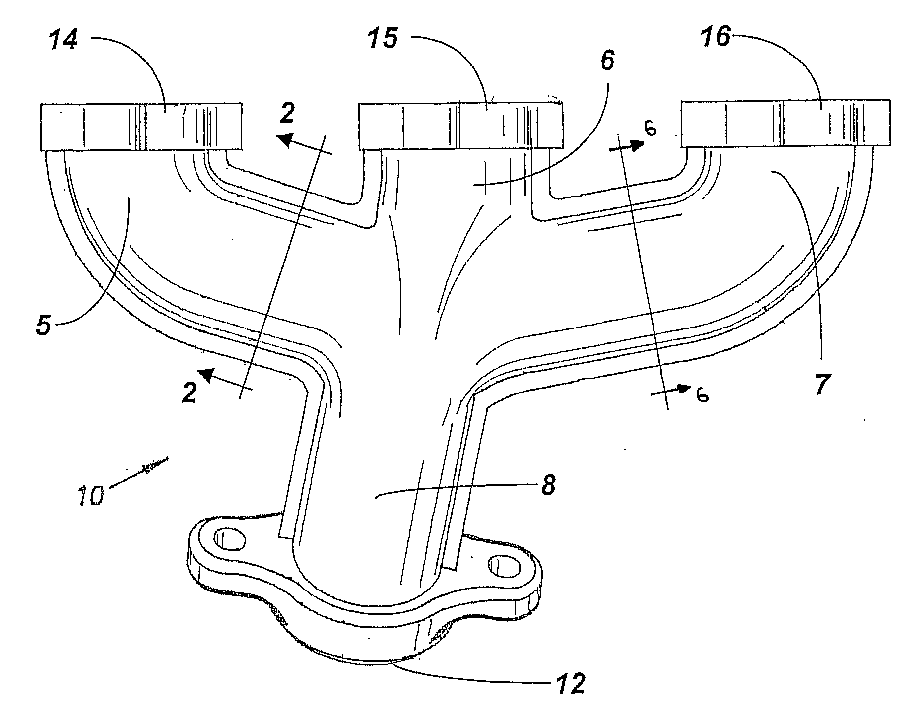
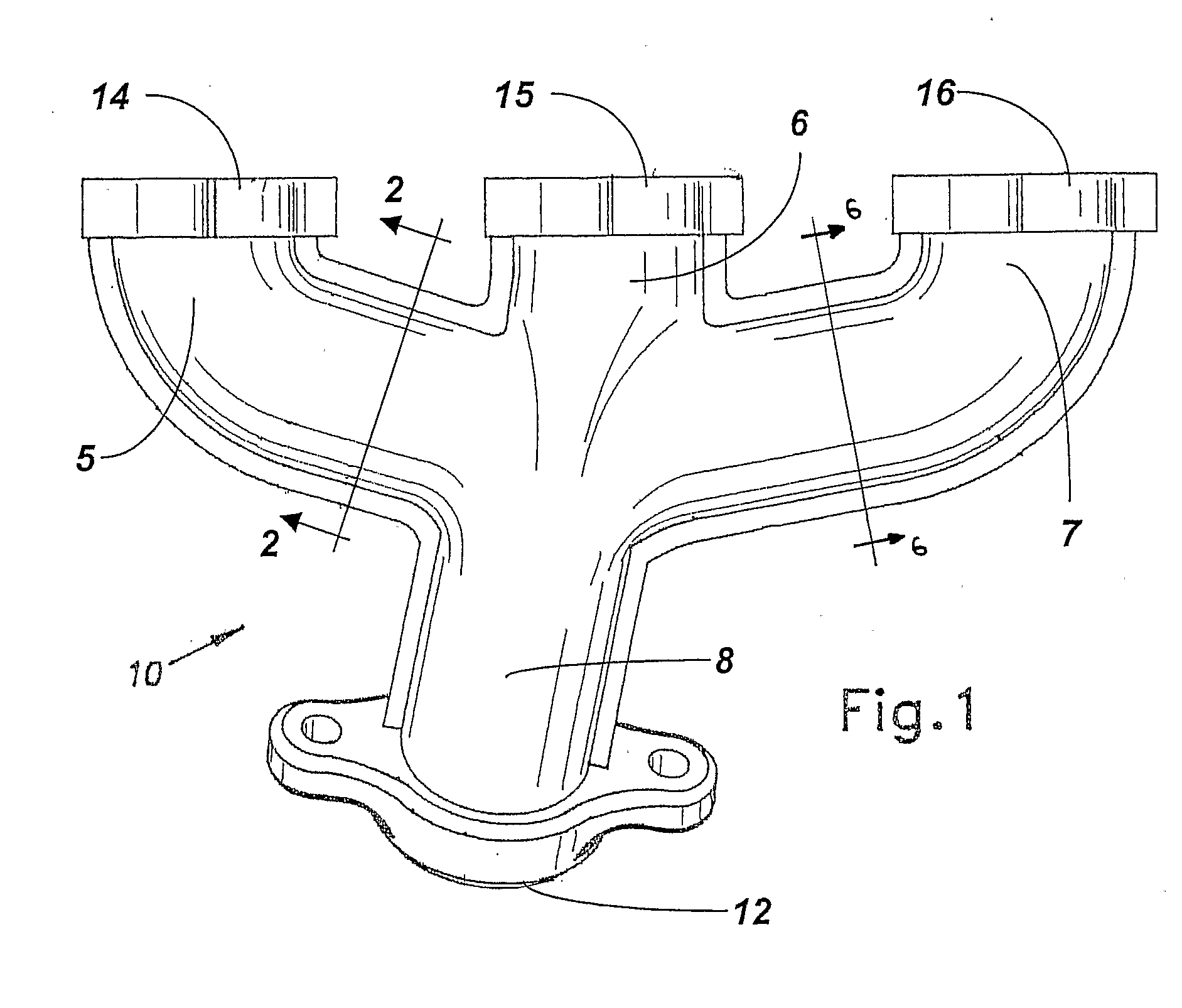
An exhaust manifold (10, 110) is provided having a ceramic inner layer (22, 32) defining an exhaust gas passageway (20), and a composite insulation zone (24, 26) that is highly thermally insulating. In one embodiment, the composite insulation zone (24) includes a plurality of metallic foils (31, 32) in alternating arrangement with layers having insulating qualities. In the composite insulation zone, the layers having insulating qualities can include ceramic layers (26), evacuated spaces, microsphere layers (37) including substantially evacuated microspheres, or a combination of these. A novel sealing arrangement also is provided for sealing the ceramic inner and metallic outer layers of a metal-encased-ceramic exhaust manifold at a location adjacent the inlet port (14, 15, 16) of a runner of the manifold. A sealing gasket (140) is substantially completely encased within or shielded by the metallic outer layer, so as not to contact the cylinder head (115) when assembled to an internal combustion engine.

Description

[0001] This application claims the benefit of U.S. Provisional Patent Application Ser. No. 60 / 549,793 filed Mar. 3, 2004, and U.S. Provisional Patent Application Ser. No. 60 / 559,119 filed Apr. 2, 2004, the contents of both of which are incorporated herein by reference in their entirety.BACKGROUND OF THE INVENTION [0002] 1. Field of the Invention [0003] The present invention relates to an exhaust manifold, and more particularly to a highly insulated exhaust manifold for an internal combustion engine. [0004] 2. Description of Related Art [0005] Catalytic converters in motorized vehicles, particularly passenger automobiles, must reach a certain temperature before they “light off.” Light off occurs when the catalytic converter begins to convert harmful pollutants by oxidizing carbon monoxide and hydrocarbons to CO2, and reducing NOx to N2 and O2. It is important to minimize the time to light off once a car is started to minimize the amount of harmful pollutants emitted to the atmosphere...

Claims


Application Information

Patent Timeline
IPC IPC(8): F01N5/02F01N7/10F01N3/02F01N13/10
CPCF01N3/20F01N13/102F01N13/148F01N2510/06F01N2310/00F01N2310/06F01N2370/02F01N13/16
Inventor SANE, AJIT Y.BUDINGER, BRUCE O.CHURBY, SCOTT A.MOORE, DAN T. IIIEUCKER, JAMES L.
Owner INTPROP HLDG
Learn More