Apparatus for generating clock pulses using a direct digital synthesizer

a technology of analog synthesizer and output clock, which is applied in the direction of oscillator, pulse automatic control, instruments, etc., can solve the problems of degrading the quality of the output clock signal and the inability to vary the output clock frequency in accordance with system performance, and achieve the effect of flexible chang

Inactive Publication Date: 2007-07-19
TRANSPACIFIC SONIC
View PDF10 Cites 17 Cited by
  • Summary
  • Abstract
  • Description
  • Claims
  • Application Information

AI Technical Summary

Benefits of technology

[0008] According to the present invention, a particular desired frequency may be produced by changing the FTW when generating the clock pulses using the DDS. This is so that the output frequency can be changed more flexibly than the conventional clock generator using a PLL. Further, better stable system clock pulses can be supplied by removing the jitter, phase noise, etc.

Problems solved by technology

However, when the clock pulses are generated using a conventional clock generator with PLL 10 such as the one described above, the output clock frequency cannot vary in accordance with system performance.
Further, the quality of the output clock signal may become degraded due to jitter and phase noise.

Method used


Image

  • Apparatus for generating clock pulses using a direct digital synthesizer
  • Apparatus for generating clock pulses using a direct digital synthesizer
  • Apparatus for generating clock pulses using a direct digital synthesizer

Examples


Embodiment Construction

[0012] In the disclosure below, an embodiment of the present invention will be described in detail with reference to the accompanying drawing.

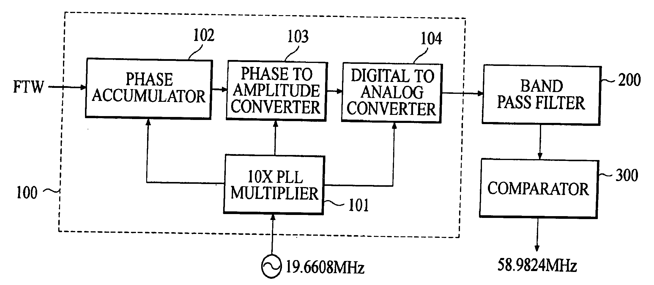
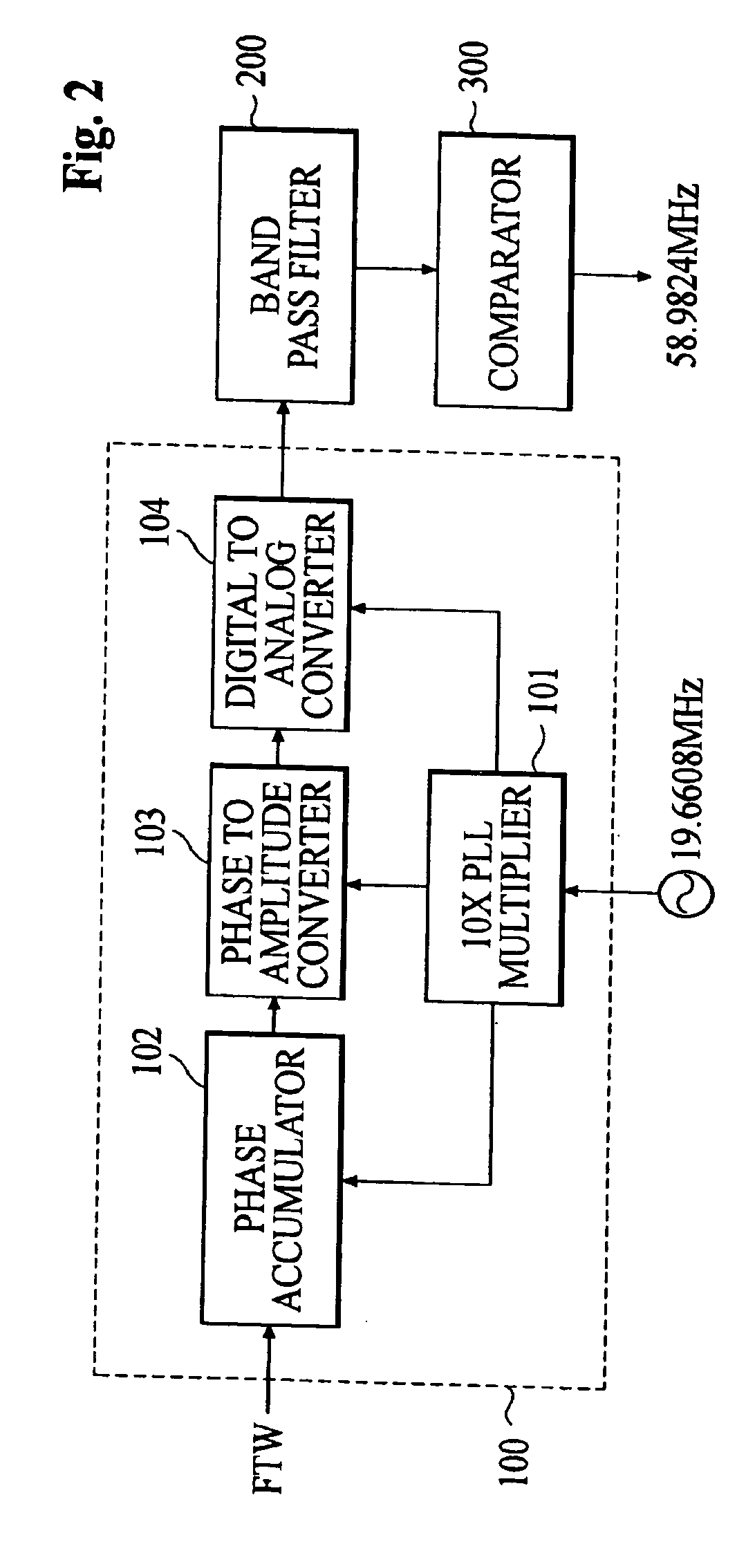
[0013]FIG. 2 is a functional block diagram of an apparatus for generating clock pulses using a DDS 100 according to one embodiment of the present invention. Referring to FIG. 2, the apparatus comprises a DDS 100 including the following elements: a 10× PLL multiplier 101; a phase accumulator 102; a phase-to-magnitude converter 103; a Digital-to-Analog (DA) converter 104; a band pass filter 200; and a comparator 300.

[0014] 10× PLL multiplier 101 within the DDS 100 receives 19.6608 MHz system reference clock pulses, converts the system reference clock pulses into 196.608 MHz DDS operation clock signals and provides the DDS operation clock signals to phase accumulator 102, phase-to-magnitude converter 103 and DA converter 104, respectively.

[0015] Phase accumulator 102 within the DDS 100, which operates using the DDS operation clock signals from...


PUM


Abstract

The present invention relates to an apparatus for generating clock pulses using a Direct Digital Synthesizer (DDS). The present invention seeks to solve the problems of the conventional clock generator using a Phase Locked Loop (PLL) circuit where the output clock frequency cannot be varied and the output clock signal is degraded because of jitter and phase noise. The claimed apparatus comprises a phase accumulator, a phase-to-magnitude converter, a Digital-to-Analog (DA) converter, a band pass filter, and a comparator, which are serially connected. A 10× PLL multiplier provides a 196.608MHz clock signal to the phase accumulator, the phase-magnitude converter and the digital analog converter, respectively. The phase accumulator also receives a Frequency Tuning Word (FTW) and using this FTW and the 196.608MHz clock, outputs a desired specific frequency value. This frequency value is processed through the phase-magnitude converter, the digital analog converter, a band pass filter and a comparator in order to become a square wave of a desired frequency with a low jitter.

Description

TECHNICAL FIELD [0001] The present invention generally relates to an apparatus for generating clock pulses using a Direct Digital Synthesizer (DDS), and more particularly to an apparatus which produces a particular desired frequency by changing a Frequency Tuning Word (FTW) when generating the clock pulses using the DDS. BACKGROUND ART [0002] As is well known, in a CDMA2000 1×base station transmit system, a Digital Up-converter Card Assembly (DUCA) is used to generate 58.9824 MHz clock pulses. These pulses are used to perform all signal processing based on 19.6608 MHz reference clock pulses. [0003] As is shown in FIG. 1, a conventional clock generator using a Phase Locked Loop (PLL) is configured to generate 58.9824 MHz clock pulses in which their phase is locked with a 19.6608 MHz by PLL 10. PLL 10 comprises a phase detector 11, a low pass filter 12, and a Voltage Controlled Oscillator (VCO) 13. [0004] However, when the clock pulses are generated using a conventional clock generato...

Claims


Application Information

Patent Timeline
Patent Type & Authority Applications(United States)
IPC IPC(8): H03B21/00H03B28/00G06F1/03H03L7/06
CPCH03L7/06G06F1/0328H03B28/00
Inventor KIM, IN GON
Owner TRANSPACIFIC SONIC
Why Eureka
Try Eureka