Projection objective for a microlithographic projection exposure apparatus

a technology of exposure apparatus and projection objective, which is applied in the direction of microlithography exposure apparatus, printers, instruments, etc., can solve the problems of not only allowing to achieve very high numerical apertures, and achieve the effects of preventing undesired drainage, high incidence angle, and preventing contamination of immersion liquid

Inactive Publication Date: 2007-07-19
CARL ZEISS SMT GMBH
View PDF10 Cites 68 Cited by
  • Summary
  • Abstract
  • Description
  • Claims
  • Application Information

AI Technical Summary

Benefits of technology

[0014] As a result of the convex curvature of the immersion liquid towards the object plane, the angles of incidence at which projection light rays impinge on the interface between an adjoining medium, e.g. the last optical element on the image side, and the immersion liquid are reduced. Thus a light ray that would be totally reflected by a flat interface can now contribute to the image, and this, in turn, allows higher numerical apertures that can also be above the refractive index of the last optical element on the image side. In this way the numerical aperture is limited only by the refractive index of the immersion liquid, but not by the refractive index of the medium that adjoins the immersion liquid on the object side.
[0016] In order to prevent an undesired drainage of the immersion liquid from the cavity that is formed by the concavely curved image-side surface of the last optical element, this surface may be surrounded circumferentially by a drainage barrier. This may, for example, be a ring that is joined to the last optical element and / or a housing of the projection objective. The ring, which may be composed, for example, of a standard lens material such as quartz glass or calcium fluoride (CaF2), but also of a ceramic or of hardened steel, is preferably provided on the inside with a coating that prevents contamination of the immersion liquid by the ring. Such a ring is also advantageous if the refractive index of the immersion liquid is equal to or smaller than the refractive index of the medium that adjoins the immersion liquid on the object side.
[0017] The image-side surface of the last optical element may be spherical. Calculations have shown that the radius of curvature may advantageously be selected to be between 0.9 times and 1.5 times and preferably 1.3 times the axial distance (i.e. vertex distance) between the this surface and the image plane. Such a configuration, which is also advantageous if the refractive index of the immersion liquid is equal to or smaller than the refractive index of the medium that adjoins the immersion liquid on the object side, has the advantage the high angles of incidence at the object side interface of the immersion liquid are avoided. Such high angles usually result in a strong sensitivity of the interface, to design and manufacturing deficiencies. From this point of view, the angles of incidence should be as small as possible. This generally requires a very large curvature (i.e. a small radius of curvature) of the object-side interface of the immersion liquid.
[0018] Another way of obtaining an interface of the immersion liquid that is convexly curved toward the object plane is to introduce an intermediate liquid between the last optical element and the immersion liquid. This intermediate liquid is not miscible with the immersion liquid and forms a curved interface in an electric field during immersion operation. Such a configuration is also advantageous if the refractive index of the immersion liquid is equal to or smaller than the refractive index of the medium that adjoins the immersion liquid on the object side.
[0021] It is furthermore advantageous if the intermediate liquid has substantially the same density as the immersion liquid since no buoyancy forces can occur and, consequently, the shape of the interface is independent of the position of the arrangement in space.
[0024] Above it has been mentioned that it may be desirable to have a strongly curved interface between the immersion liquid and the medium adjoining to the object side, because this simplifies the correction of imaging aberrations. However, it has also significant advantages if the curvature of this interface is small. This is because a large curvature generally leads to the formation of a cavity within the last optical element. Such a cavity has several drawbacks. For example, it favors the occurrence of undesired turbulences within the cavity if a flow of the immersion liquid has to maintained, for example for reasons of temperature stability and for purifying the liquid. Furthermore, highly refractive immersion liquids have a somewhat higher absorption than lens materials. For that reasons the maximum geometrical path lengths within the immersion liquid should be kept small. Finally, a small curvature simplifies the access to the image side surface of the last optical element for cleaning purposes.

Problems solved by technology

Immersion operation, however, does not only allow to achieve very high numerical apertures and, consequently, a smaller resolution, but it also has a favorable effect on the depth of focus.

Method used


Image

  • Projection objective for a microlithographic projection exposure apparatus
  • Projection objective for a microlithographic projection exposure apparatus
  • Projection objective for a microlithographic projection exposure apparatus

Examples


Embodiment Construction

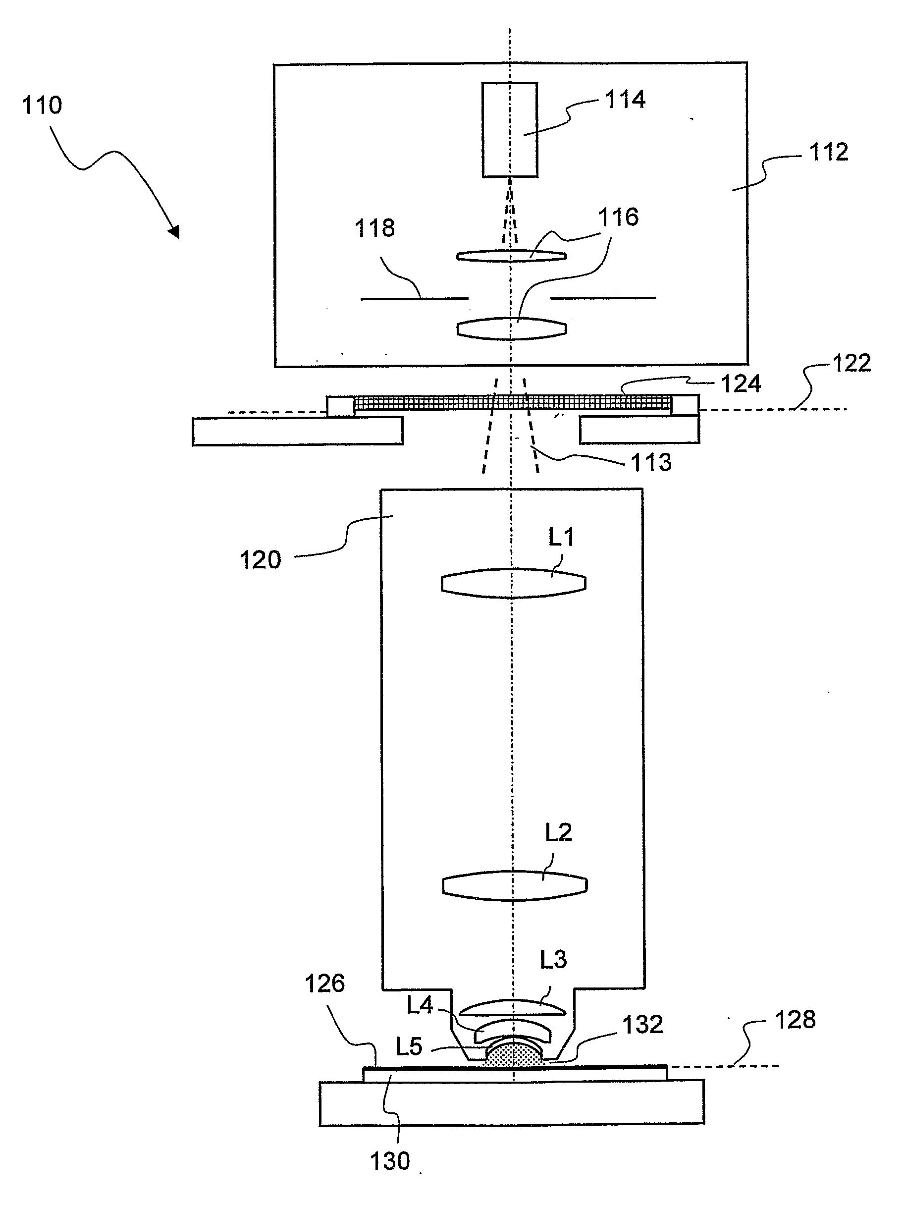
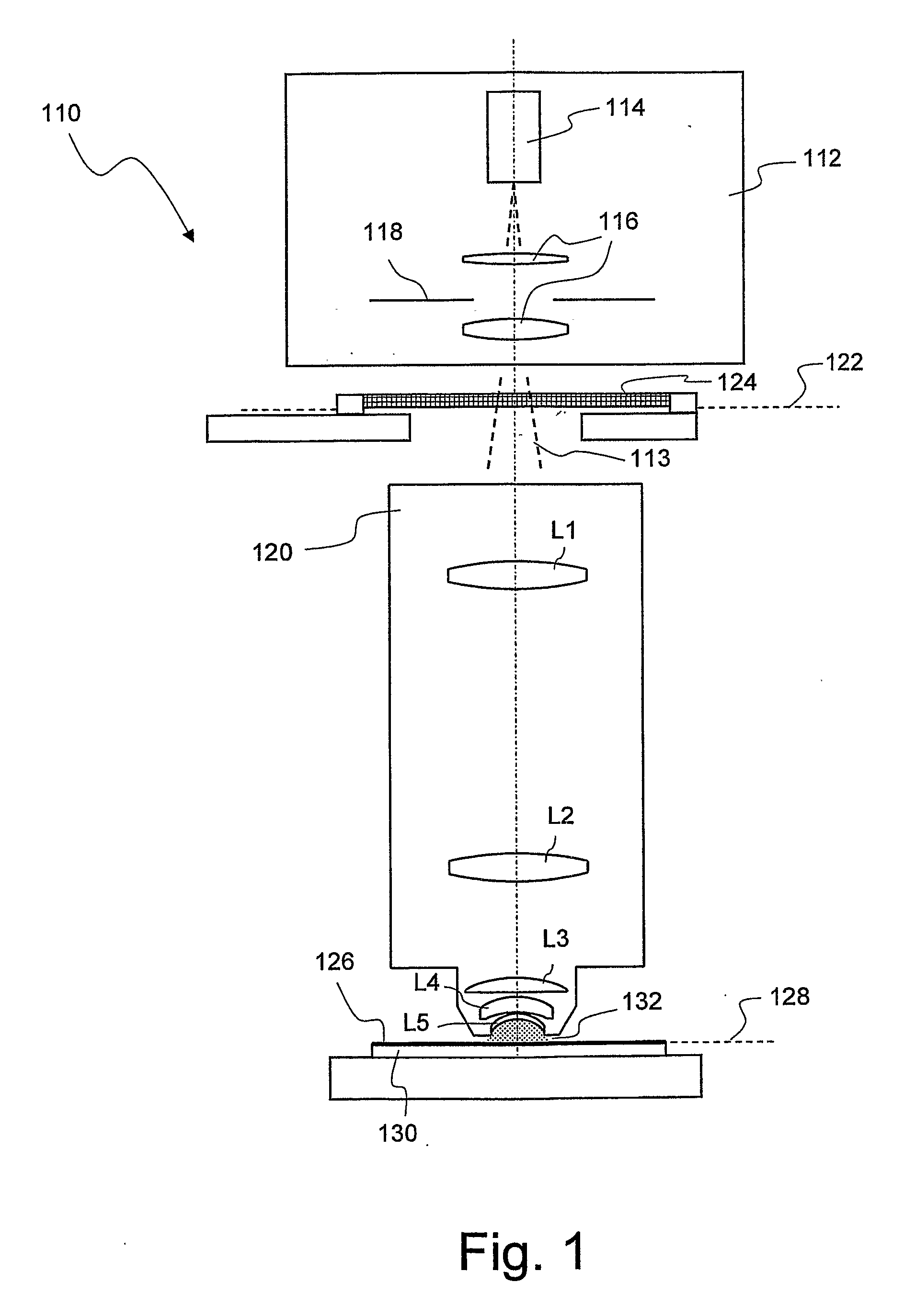
[0037]FIG. 1 shows a meridian section through a microlithographic projection exposure apparatus denoted in its entirety by 110 in a considerably simplified view that is not to scale. The projection exposure apparatus 110 comprises an illuminating system 112 for generating projection light 113 including a light source 114, illumination optics indicated by 116 and a diaphragm 118. In the exemplary embodiment shown, the projection light 113 has a wavelength of 193 nm.

[0038] The projection exposure apparatus 110 furthermore includes a projection objective 120 that comprises a multiplicity of lens elements, of which, for the sake of clarity, only a few are indicated by way of example in FIG. 1 and are denoted by L1 to L5. The projection objective 120 images a mask 124 disposed in an object plane 122 of the projection objective 120 on a reduced scale on a photosensitive layer 126. The layer 126, which may be composed of a photoresist, is disposed in an image plane 128 of the projection o...


PUM

PropertyMeasurementUnit
wavelengthsaaaaaaaaaa
wavelengthaaaaaaaaaa

Abstract

A projection objective of a microlithographic projection exposure apparatus (110) is designed for immersion operation in which an immersion liquid (134) adjoins a photosensitive layer (126). The refractive index of the immersion liquid is greater than the refractive index of a medium (L5; 142; L205; LL7; LL8; LL9). that adjoins the immersion liquid on the object side of the projection objective (120; 120′; 120″). The projection objective is designed such that the immersion liquid (134) is convexly curved towards the object plane (122) during immersion operation.

Description

BACKGROUND OF THE INVENTION [0001] 1. Field of the Invention [0002] The invention relates to microlithographic projection exposure apparatuses as are used to manufacture large-scale integrated electrical circuits and other microstructured components. More particular, the invention relates to a projection objective of such an apparatus that is designed for immersion operation. [0003] 2. Description of Related Art [0004] Integrated electrical circuits and other microstructured components are normally produced by applying a plurality of structured layers to a suitable substrate, which may be, for example, a silicon wafer. To structure the layers, they are first covered with a photoresist that is sensitive to light of a certain wavelength range. The wafer coated in this way is then exposed in a projection exposure apparatus. In this operation, a pattern of structures contained in a mask is imaged on the photoresist with the aid of a projection objective. Since the imaging scale is gener...

Claims


Application Information

Patent Timeline
Patent Type & Authority Applications(United States)
IPC IPC(8): G03B27/00G03F7/20
CPCG03F7/70225G03F7/70241G03F7/70966G03F7/70958G03F7/70341G03F7/20
Inventor KNEER, BERNHARDWABRA, NORBERTGRUNER, TORALFEPPLE, ALEXANDERBEDER, SUSANNESINGER, WOLFGANG
Owner CARL ZEISS SMT GMBH
Why Eureka
Try Eureka