Vaporizer, film forming apparatus including the same, method of vaporization and method of forming film

a technology of vaporizer and film forming apparatus, which is applied in the direction of coating, chemical vapor deposition coating, coating process, etc., can solve the problems of hardly realizing failure to withstand long-term use, and assumption that more than 256m bits will be hardly realized

Inactive Publication Date: 2007-07-19
YAMOTO HISAYOSHI +5
View PDF0 Cites 380 Cited by
  • Summary
  • Abstract
  • Description
  • Claims
  • Application Information

AI Technical Summary

Benefits of technology

[0126] wherein the disperser is provided with a radiatio

Problems solved by technology

Problematic in development of DRAM is a storage capacitance accompanying to scale-down for such a memory.
However, regarded as problems in such three-dimensional structures are an increased number of procedures due to a complicated process and a deteriorated yield due to increased step height differences, thereby leading to an assumption that more than 256M bits will be hardly realized.
However, this technique is problematic in that the metal filter is brought to be clogged by vaporization over several hours, and thus fails to withstand long-term usage.
However, also this technique is problematic in that the small hole is brought to be clogged by usage over several hours, and thus fails to withstand long-term usage.
Further, in case that the material solution is a mixed solution of a plurality of organometallic complexes such as Sr(DPM)2/THF, Bi(C6H5)3/THF, and Ta(OC2H5)5/THF, and that the mixed solution is to be vaporized by heating, the solvent (THF i

Method used


Image

  • Vaporizer, film forming apparatus including the same, method of vaporization and method of forming film
  • Vaporizer, film forming apparatus including the same, method of vaporization and method of forming film
  • Vaporizer, film forming apparatus including the same, method of vaporization and method of forming film

Examples


embodiments

Embodiment 1

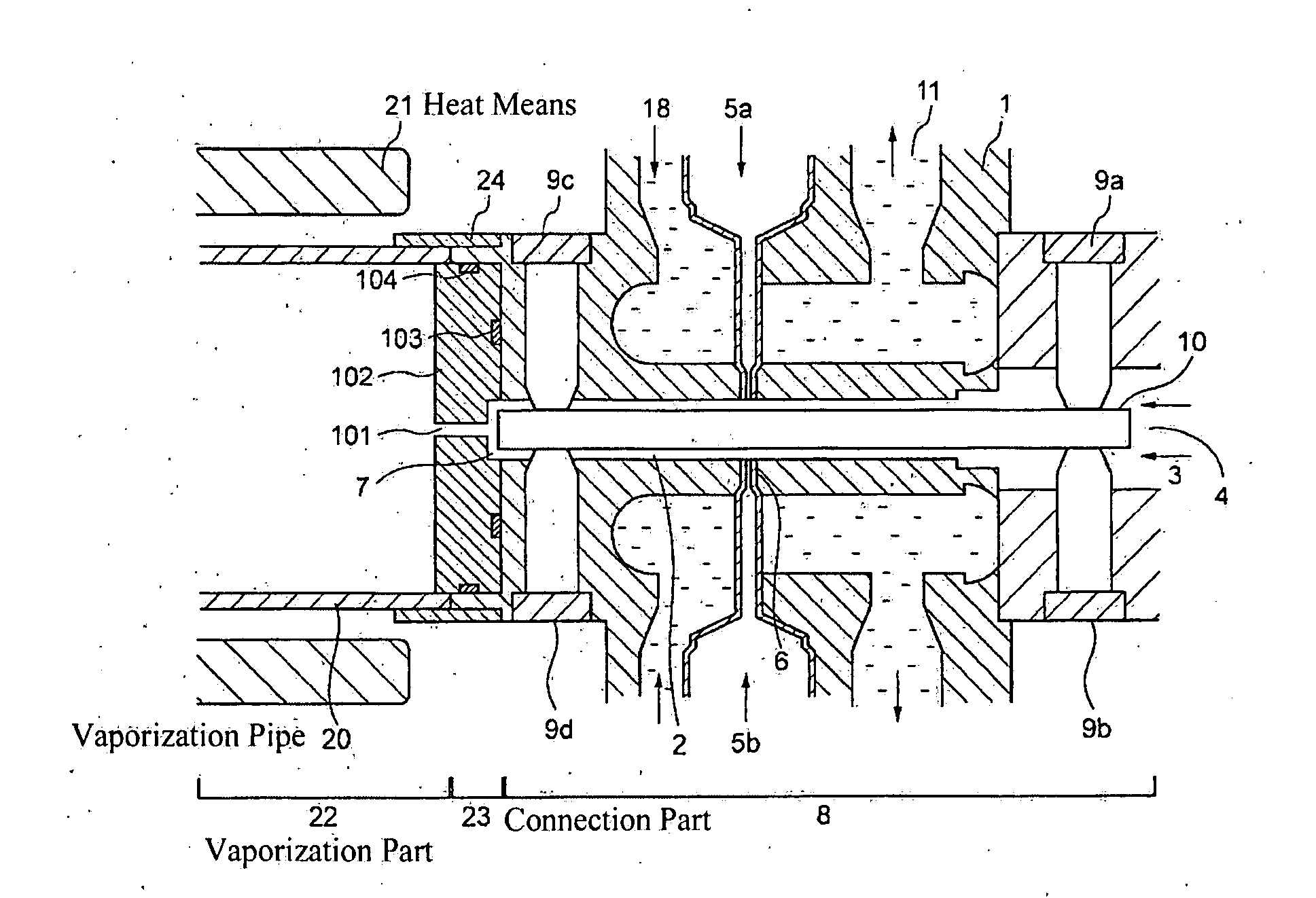
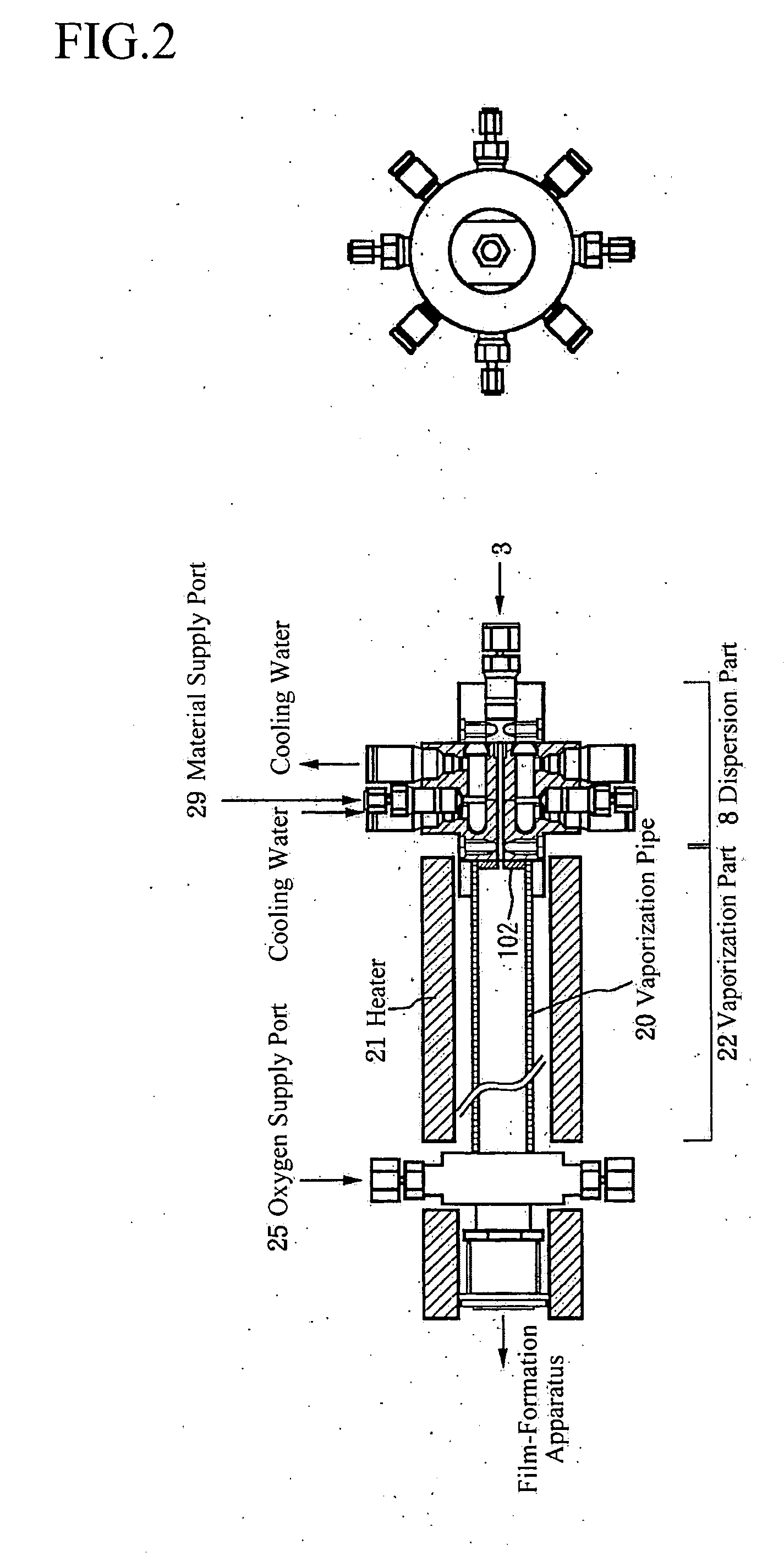
[0221]FIG. 1 shows an MOCVD oriented vaporizer according to an embodiment 1.

[0222] This embodiment has:

[0223] (i) a dispersion part 8 including:

[0224] a gas passage 2 formed within a dispersion part body 1 constituting the dispersion part,

[0225] a gas inlet 4 for introducing a pressurized carrier gas 3 into the gas passage 2,

[0226] means (material supply ports) 6 for supplying material solutions 5 into the carrier gas passing through the gas passage 2, to thereby atomize the material solutions 5 into a mist state,

[0227] a gas outlet 7 for feeding the carrier gas including the material solutions 5 in the mist state (i.e., a material gas) to a vaporization part 22, and

[0228] means (cooling water) 18 for cooling the carrier gas flowing through the gas passage 2; and

[0229] (ii) the vaporization part 22 including:

[0230] a vaporization pipe 20 having one end connected to a reaction tube of an MOCVD apparatus, and the other end connected to the gas outlet 7 of the dis...

embodiment 2

[0272]FIG. 5 shows an MOCVD oriented vaporizer according to an embodiment 2.

[0273] In this embodiment, the radiation prevention part 102 is formed at its outer periphery with a cooling water passage 106, and the connection part 23 is provided with cooling means 50 for cooling the radiation prevention part 102.

[0274] Further, there is provided a recess 107 around the small hole 101.

[0275] Other aspects are the same as those of the embodiment 1.

[0276] In this embodiment, there was found a more satisfactory correspondence between the detected product and the product to be given by the reaction formula considered based on the reaction theory, than the case of the embodiment 1.

[0277] Further, as a result of measurement of a sticked amount of carbides at an outer surface at the gas outlet 7 side of the dispersion part body 1, the sticked amount of carbides was about ⅓ times that in the case of the embodiment 1.

embodiment 3

[0278]FIG. 6 shows an MOCVD oriented vaporizer according to an embodiment 3.

[0279] In this embodiment, the radiation prevention part 102 is provided with a taper 51. Such a taper eliminates a dead zone there, to enable prevention of retention of materials.

[0280] Other aspects are the same as those of the embodiment 2.

[0281] In this embodiment, there was found a more satisfactory correspondence between the detected product and the product to be given by the reaction formula considered based on the reaction theory, than the case of the embodiment 2.

[0282] Further, as a result of measurement of a sticked amount of carbides at an outer surface at the gas outlet 7 side of the dispersion part body 1, the sticked amount of carbides was nearly absent.


PUM

PropertyMeasurementUnit
Diameteraaaaaaaaaa
Pressureaaaaaaaaaa
Diameteraaaaaaaaaa

Abstract

It is aimed at providing a vaporization apparatus and a vaporization method capable of keeping track of a progressive condition of clogging of the apparatus. It is also aimed at providing a vaporization apparatus and a vaporization method capable of eliminating clogging prior to occurrence of complete clogging, without disassembling the apparatus. It provides a vaporization apparatus for introducing a carrier gas from one end of a gas passage and for feeding, the carrier gas including a material solution, from the other end of the gas passage to a vaporization part to thereby vaporize the material solution, characterized in that a mass flow controller (MFC) is provided at the one end of the gas passage, and means for detecting a pressure within the gas passage is provided. The vaporization apparatus is characterized in that the same is provided with means for introducing a chemical solution capable of dissolving therein matters deposited or sticked to the inside of the gas passage, into the gas passage.

Description

TECHNICAL FIELD [0001] The present invention relates to a vaporizer, a vaporization method, a film-formation apparatus, and other various devices preferably usable for MOCVD, for example. BACKGROUND ART [0002] Problematic in development of DRAM is a storage capacitance accompanying to scale-down for such a memory. Because capacitances are required to be at the same level as the former generation from a standpoint of soft error and the like, some countermeasures are necessary. As one countermeasure, it has been contemplated to increase each capacitor area by adopting a three-dimensional structure which is exemplarily called stack structure / trench structure for cell structures of 4M or more, though planar structures have been used in cell structures of 1M or less. Also, adopted as dielectric films are stacked films (which are typically called ON films) obtained by stacking thermal oxidation films and CVD nitride films on poly-Si, instead of thermal oxidation films on substrate Si. In ...

Claims


Application Information

Patent Timeline
IPC IPC(8): C23C16/00C23C16/448H01L21/31
CPCC23C16/448H01L21/02271
Inventor YAMOTO, HISAYOSHIAKUTO, KAZUYANAGAOKA, KENKOBAYASHI, HITOSHISHOJI, MASAFUMIFUKUGAWA, MITSURU
Owner YAMOTO HISAYOSHI
Why Eureka
Try Eureka