Heath monitoring method and apparatus for composite materials

a composite material and health monitoring technology, applied in the direction of resistance/reactance/impedence, line-transmission details, instruments, etc., can solve the problems of affecting the health the damage of the composite material, and the deformation of the polymer material with age, so as to achieve the effect of improving strength and reducing volume requirements

Inactive Publication Date: 2007-07-19
WATKINS JR KENNETH S +1
View PDF1 Cites 59 Cited by
  • Summary
  • Abstract
  • Description
  • Claims
  • Application Information

AI Technical Summary

Benefits of technology

[0012] Another object is to provide a heath monitoring method for composites which utilizes simple, inexpensive equipment.
[0013] Another object is to provide a heath monitoring method for composites which does not require extensive training for field use.
[0021] In the preferred embodiments, conductive particles are selected to be chemically inert for the matrix under the expected environmental conditions of the component. Carbon particles such as those in the form of carbon black provide a low-cost conductive filler for many applications. In other applications, other carbon forms such as carbon nanotubes provide advantages such as lower volume requirements for the desired initial resistivity, and strength improvements in a composite. In still other applications, metallic particles such as silver, aluminum, nickel and copper may be used. Metallic oxides and semi-conductor materials may also be used.

Problems solved by technology

Polymeric materials degrade with age, especially in severe environmental conditions.
While these methods are effective for some applications, they suffer several serious disadvantages.
For example, visual inspections are useful only on components with full visual access, and are not effective for flaws below the surface of the component.
Radiography requires access to the components and it is time consuming and requires special training for evaluation of the results.
The equipment is very expensive and subject to considerable controls to prevent radiation damage to personnel and equipment.
All of these methods are effective only in detecting actual mechanical flaws such as cracks, and are not effective in predicting deterioration of the composite prior to development of the mechanical flaws.

Method used


Image

  • Heath monitoring method and apparatus for composite materials
  • Heath monitoring method and apparatus for composite materials
  • Heath monitoring method and apparatus for composite materials

Examples


Embodiment Construction

[0040] The following is a description of the preferred embodiments of a condition sensor for composite materials and a method for determining the condition of the composite material by measurement of the resistance of the condition sensor.

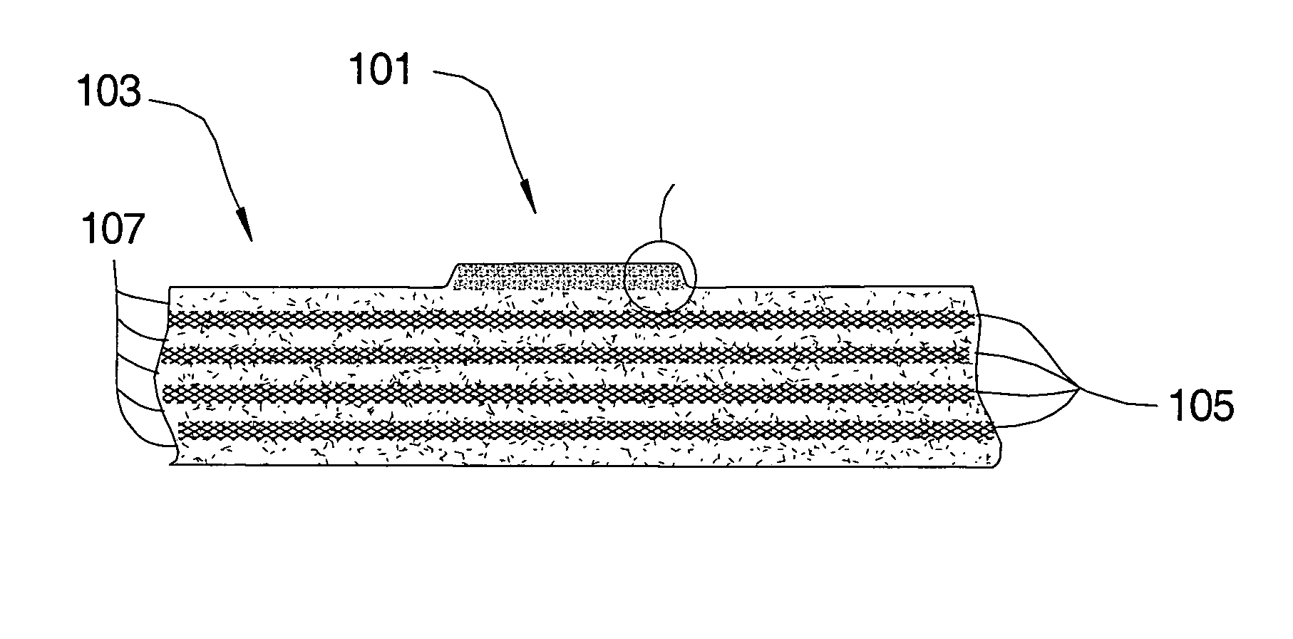
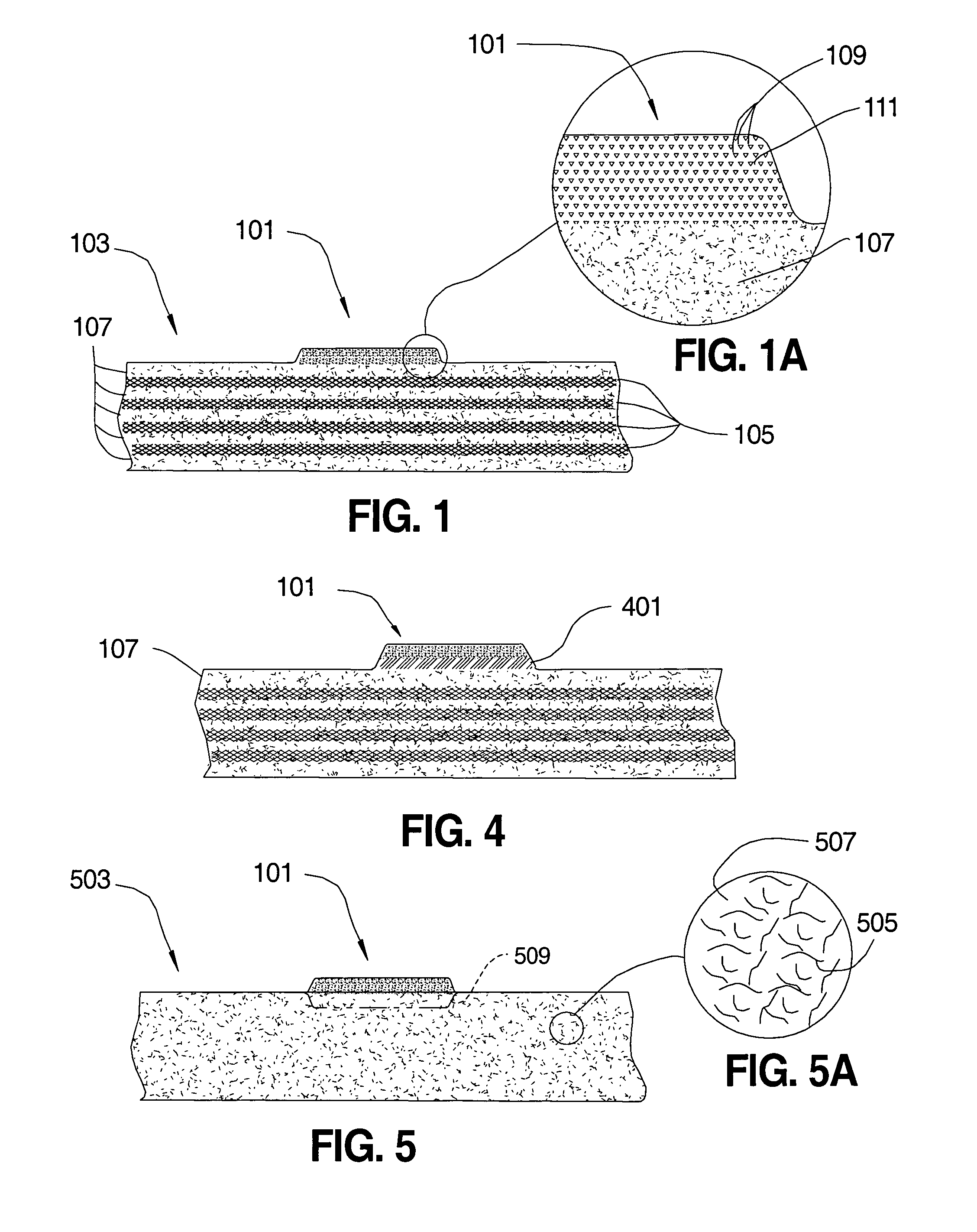
[0041]FIG. 1 is a cross section drawing of a preferred embodiment of a conductive composite condition sensor 101 for a composite material 103. Composite material 103 is made of a reinforcement fiber such as reinforcement fabric 105 dispersed in a thermoplastic or thermoset polymer matrix 107. Reinforcement fabrics include fibers made of metallic, carbon, glass, boron, ceramic and polymeric fibers. The reinforcement fibers may be in woven or non-woven mats, or they may be dispersed in the matrix. Matrix material 107 includes thermoplastic materials such as polyamides, polyolefins and fluoropolymers, and thermosets such as epoxies and polyesters.

[0042] As shown best in FIG. 1A, condition sensor 101 consists of conductive particles 109 such as carbo...


PUM

PropertyMeasurementUnit
electrical resistivityaaaaaaaaaa
electrical propertyaaaaaaaaaa
resistanceaaaaaaaaaa

Abstract

An in-situ method for monitoring the heath of a composite component (103) utilizes a condition sensor (101) made of electrically conductive particles (109) dispersed in a polymeric matrix (111). The sensor is bonded or otherwise formed on the matrix surface of the composite material. Age-related shrinkage of the sensor matrix results in a decrease in the resistivity of the condition sensor. Correlation of measured sensor resistivity with data from aged specimens allows indirect determination of mechanical properties and remaining age of the composite component.

Description

[0001] This Application Claims benefit of U.S. Provisional Application No. 60 / 547,327 filed Feb. 24, 2004 and PCT Application No. PCT / US2005 / 005604 filed Feb. 23, 2005.[0002] This application resulted, in part, from research funded by the U. S. Department of Energy. Certain rights for any intellectual property resulting from this application may apply to the Government of the United States.FIELD OF THE INVENTION [0003] The present invention relates to health monitoring of composite materials, and, more particularly, to health monitoring of polymeric composite materials by use of conductive composite age sensors. BACKGROUND OF THE INVENTION [0004] Polymeric materials degrade with age, especially in severe environmental conditions. Degradation may be (1) chemical, such as chain scission and cross-linking, (2) physical, such as loss of volatile fractions and environmentally induced macroscopic changes such as crystallinity, and physical changes due to a tendency for thermodynamic equil...

Claims


Application Information

Patent Timeline
Patent Type & Authority Applications(United States)
IPC IPC(8): G01N27/00
CPCG01N27/041G01N27/20
Inventor WATKINS, KENNETH S. JR.MORRIS, SHELBY J.
Owner WATKINS JR KENNETH S
Why Eureka
Try Eureka