Balanced surface acoustic wave filter
- Summary
- Abstract
- Description
- Claims
- Application Information
AI Technical Summary
Benefits of technology
Problems solved by technology
Method used
Image

Examples
first preferred embodiment
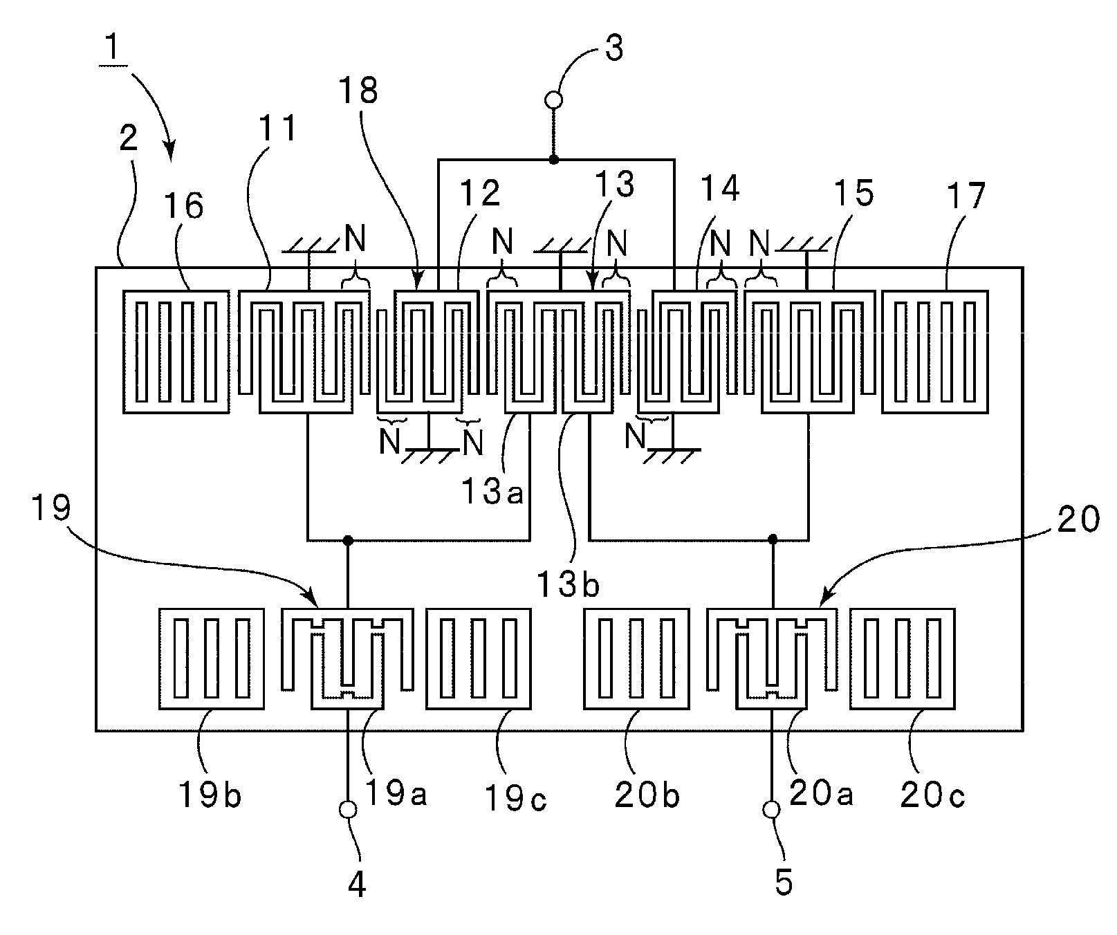
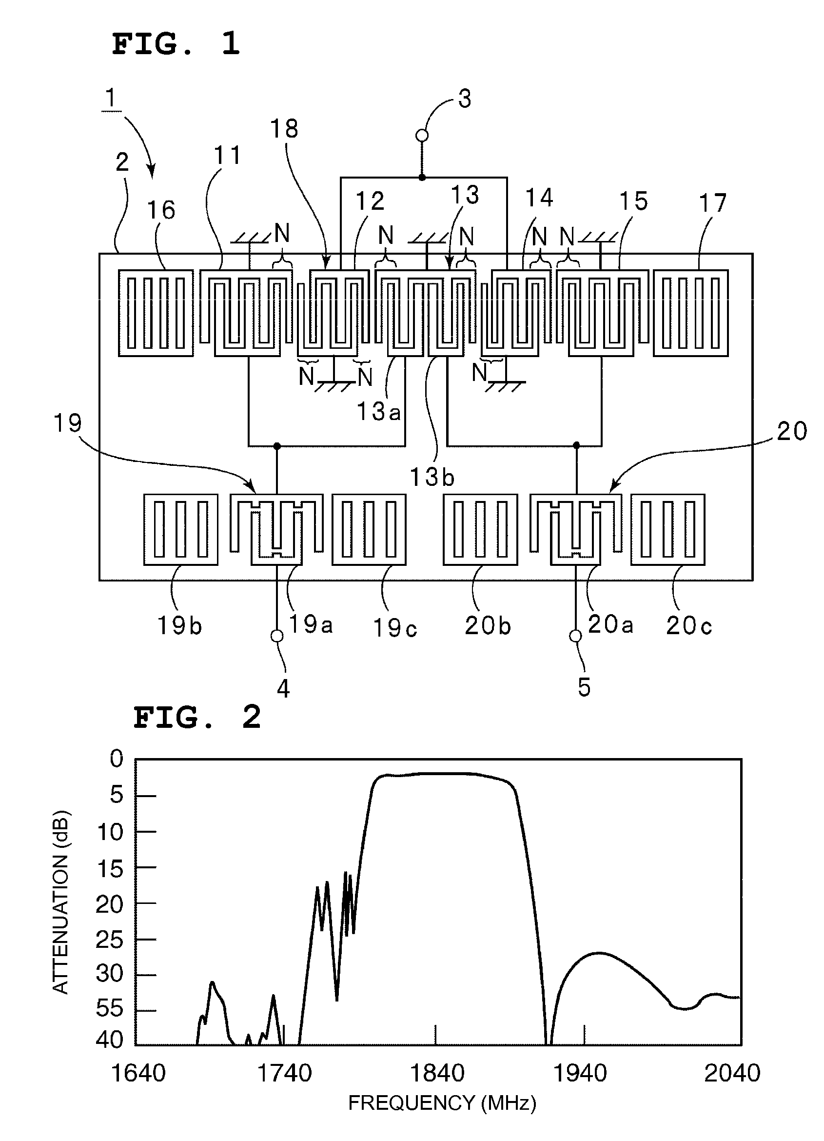
[0031]FIG. 1 is a plan view schematically illustrating a surface acoustic wave filter according to a preferred embodiment of the present invention.
[0032] A surface acoustic wave filter 1 according to the present preferred embodiment includes a plate like piezoelectric substrate 2. According to the present preferred embodiment, the piezoelectric substrate 2 is preferably composed of a 40±5° Y-cut X-propagation LiTaO3 substrate. The surface acoustic wave filter 1 is a balanced surface acoustic wave filter including an unbalanced terminal 3, a first balanced terminal 4, and a second balanced terminal 5 and has a balanced-unbalanced conversion function. In addition, the surface acoustic wave filter 1 according to the present preferred embodiment is used for a DCS reception band-pass filter. The impedance of the unbalanced terminal 3 is preferably about 50 Ω. The impedances of the first balanced terminal 4 and the second balanced terminal 5 are preferably about 100 Ω.
[0033] A longitudi...
second preferred embodiment
[0066]FIG. 5 is a plan view schematically illustrating the electrode structure of a surface acoustic wave filter according to a second preferred embodiment of the present invention.
[0067] According to the second preferred embodiment, a surface acoustic wave filter 21 includes first and second surface acoustic wave filter units 23 and 24 provided on a piezoelectric substrate 22. Each of the first and second surface acoustic wave filter units 23 and 24 is a 5-IDT longitudinally coupled resonator type balanced surface acoustic wave filter. The second surface acoustic wave filter unit 24 is connected in a cascade arrangement to the first surface acoustic wave filter unit 23. According to this preferred embodiment of the present invention, as described above, the two surface acoustic wave filter units 23 and 24 may be longitudinally connected in a two-stage arrangement.
[0068] The first surface acoustic wave filter unit 23 includes first to fifth IDTs 31 to 35 disposed along the surface...
third preferred embodiment
[0075]FIG. 6 is a plan view schematically illustrating the electrode structure of a surface acoustic wave filter according to a third preferred embodiment of the present invention. In a surface acoustic wave filter 61 according to the third preferred embodiment, a second surface acoustic wave filter unit 63 is provided on a piezoelectric substrate 62 in the previous stage of a first surface acoustic wave filter unit 64. The second surface acoustic wave filter unit 63 is connected in a cascade arrangement to the first surface acoustic wave filter unit 64 in a two-stage arrangement.
[0076] The second surface acoustic wave filter unit 63 includes sixth to tenth IDTs 71 to 75 disposed along the surface acoustic wave propagation direction. In addition, the second surface acoustic wave filter unit 63 includes reflectors 76 and 77 disposed at either end of an area at which the IDTs 71 to 75 are disposed in the surface acoustic wave propagation direction. The IDTs 71 to 75 include the narro...
PUM
 Abstract
Description
Claims
Application Information
 - R&D
- Intellectual Property
- Life Sciences
- Materials
- Tech Scout
- Unparalleled Data Quality
- Higher Quality Content
- 60% Fewer Hallucinations
Browse by: Latest US Patents, China's latest patents, Technical Efficacy Thesaurus, Application Domain, Technology Topic, Popular Technical Reports.
© 2025 PatSnap. All rights reserved.Legal|Privacy policy|Modern Slavery Act Transparency Statement|Sitemap|About US| Contact US: help@patsnap.com