
Process for accurate location determination in GPS positioning system

a positioning system and location technology, applied in satellite radio beaconing, measurement devices, instruments, etc., can solve the problems of difficult to find, difficult to find, and difficult to find,

Active Publication Date: 2007-07-26
MAGELLAN SYST JAPAN
View PDF3 Cites 32 Cited by
  • Summary
  • Abstract
  • Description
  • Claims
  • Application Information

AI Technical Summary

Problems solved by technology

The ability of the receiver to perform these tasks is often limited by the presence of buildings, mountains, foliage, or other obstacles that block or severely attenuate the received satellite signals.
In addition, a considerable length of time may be required to search for and acquire the satellite signals, read the navigational data contained in them, and make the measurements needed to establish the position of the user.
These limitations are particularly serious when the user needs to establish his or her position in an emergency situation.
Standard satellite navigational receivers usually take too much time to perform the operations needed to obtain a position of the user, which might be as much as several minutes or more.
Additionally, it is often the case that the satellite signals at the location of the emergency are too weak to be usable by a standalone receiver.
This is not at all uncommon inside a building whose walls severely attenuate the electromagnetic radiation from the satellites.
In a standard GPS receiver the above sequence of operations can be quite time consuming; In particular, the search for satellites in Step 3 may require several minutes or even more, depending on a number of conditions.
A second source of frequency uncertainty occurs when the receiver does not have recent (no more than 2 hours old) ephemeris data, or does not have sufficiently accurate approximate a-priori knowledge of its position to know what signal Doppler shift to expect (the Doppler shift can change by approximately 1 Hz / km worst case).
In addition to the possibility of a lengthy search to acquire the satellites, the demodulation of the navigation data stream from each satellite to obtain ephemeris and time information in Step 8 also can take a considerable length of time.
A more serious problem in extracting the time and ephemeris data from the navigation message occurs when the GPS signal is too weak to permit reliable demodulation of the navigation message data bits.
In urban canyons and inside buildings the C / No can easily fall below this value, rendering the user=s standard GPS receiver inoperative because it can no longer obtain error-free ephemeris and time data needed for positioning.
For the reasons described above the standard method of GPS positioning with an autonomous (unassisted) receiver is not suitable in applications where rapid and reliable position determination is needed, particularly in weak signal environments.
First, it is not desirable for the rover to spend precious time reading the time information from the received signal, and second, the signal may be too weak to permit this to occur.
Such a timing signal cannot be used to determine time of signal transmission from the satellite, since the time of signal transmission differs from absolute time at the server or the rover by an unknown amount (even if the timing signal could be used for this purpose it would be difficult or impossible for a communication link to provide it to the rover at the required accuracy of tens of nanoseconds).
However, the 1-millisecond time ambiguity remains unresolved.
Unfortunately, however, the communication link, such as a cell phone link typically available for this purpose, contains unknown and variable transmission delays occur due to packetizing and queuing of data from the server.
These unpredictable delays often are much too large to be of use for determining satellite positions.
However, the modification of such a communication link (for example, a cellular telephone network) to provide a sufficiently accurate timing signal is undesirable because it can be far too costly and is generally not appealing to providers of such services.

Method used


Image

  • Process for accurate location determination in GPS positioning system
  • Process for accurate location determination in GPS positioning system
  • Process for accurate location determination in GPS positioning system

Examples


Embodiment Construction

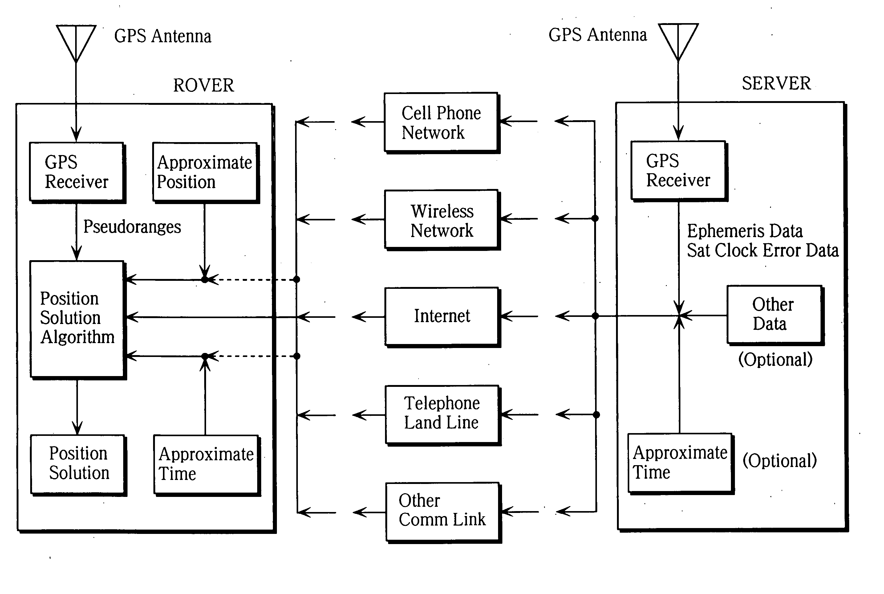
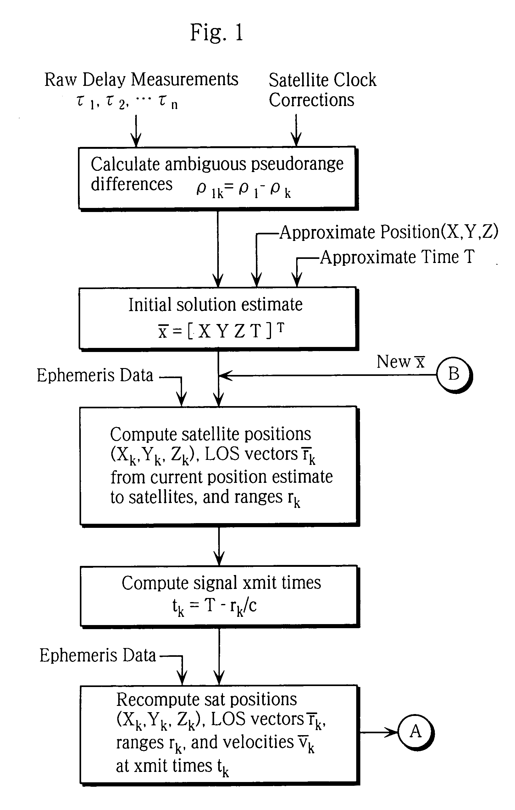
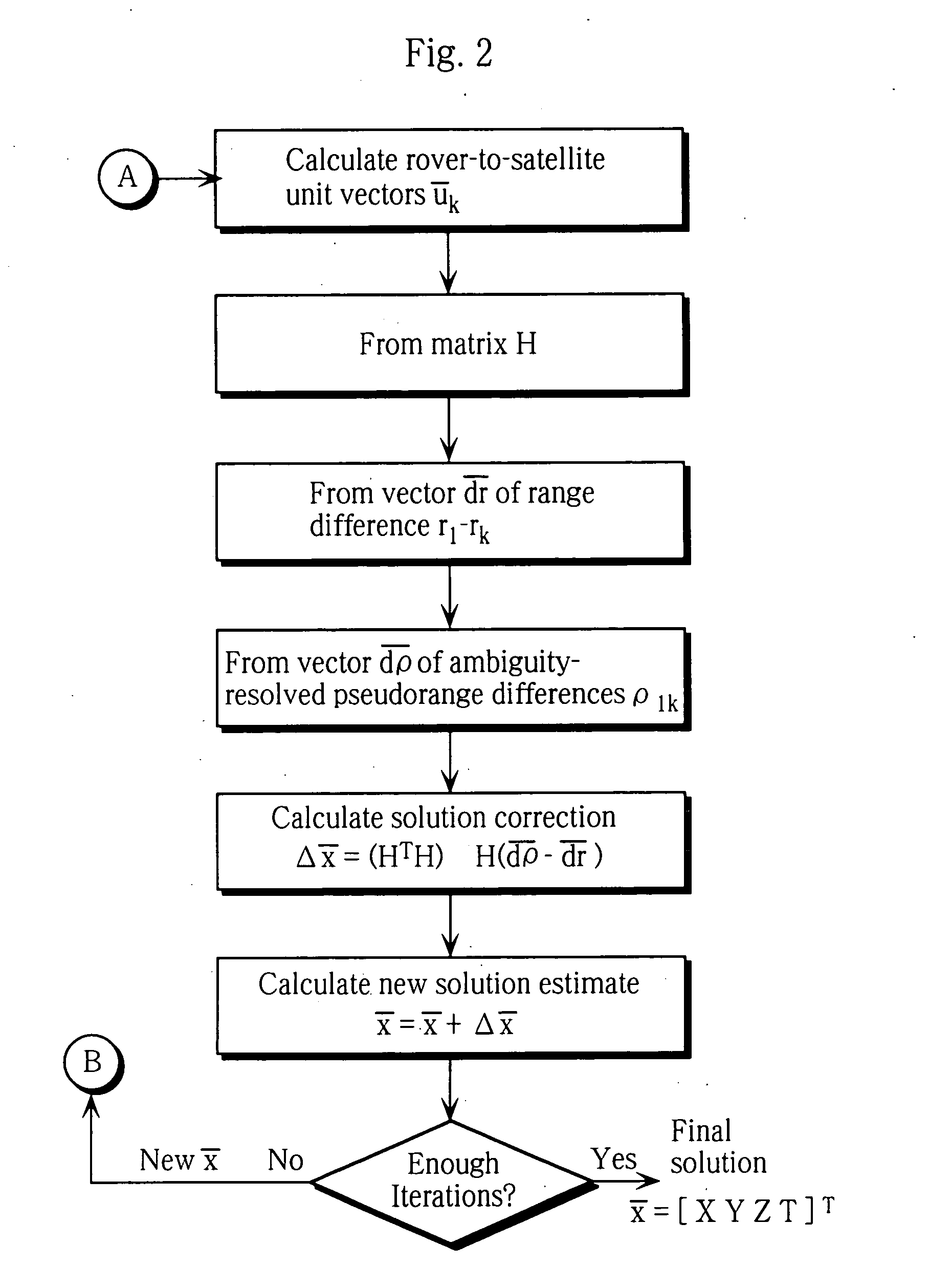
[0037] The present invention solves the problem of obtaining unambiguous time, with an error generally not exceeding several milliseconds, by using at least one additional satellite beyond what is normally needed for positioning. The rover obtains time neither from the navigation message nor from the server. Instead, time is treated as an additional variable which can be determined directly from the navigation solution, although not as accurately as that based on timing data contained in the navigation message. Navigation solutions in unassisted receivers generally solve for position (three coordinates X, Y, and Z) and receiver clock error B. In such receivers the solution for receiver clock error B can be used to calibrate the receiver clock and thereby obtain very accurate time, but to get this degree of accuracy the navigation solution requires that the receiver read timing data directly from the GPS signal. In contrast, the present invention includes unambiguous time t as the fo...


PUM


Abstract

A process is provided for accurate location determination in assisted satellite-based positioning systems in which a base station (server) transmits assisting information to the user's receiver (rover). Signals from at least 5 satellites are used for 3-dimensional positioning. Pseudorange measurements are made in a system of equations having a minimum set of unknowns X,Y,Z, and T. (X,Y,Z) is the 3D rover position in a predefined coordinate system, and T is the time at which simultaneous measurements are made to determine pseudoranges to all satellites. The position of each satellite is a vector-valued function fk (T) of said time T, where fk is determined from satellite ephemeris data or its equivalent, sent to the rover over a communication link, as well as from knowledge of the approximate position of the rover.

Description

BACKGROUND OF INVENTION [0001] Satellite positioning systems, such as the Global Positioning System (GPS) or its European counterpart, Galileo, can determine the position of the user anywhere on Earth with accuracies that range from tens of meters using autonomous low-cost receivers to the centimeter level using survey-grade receivers which operate in conjunction with a base station (differential operation). In both of these modes of operation, the receiver must acquire and track the signals from a plurality of satellites in order to make measurements of the distance from the receiver to each of the satellites in view. The ability of the receiver to perform these tasks is often limited by the presence of buildings, mountains, foliage, or other obstacles that block or severely attenuate the received satellite signals. In addition, a considerable length of time may be required to search for and acquire the satellite signals, read the navigational data contained in them, and make the m...

Claims


Application Information

Patent Timeline
IPC IPC(8): G01S5/14G01S19/25G01S19/42
CPCG01S19/42G01S19/258
Inventor WEILL, LAWRENCE R.
Owner MAGELLAN SYST JAPAN
Learn More