Method for producing a wheel, disc

a disc and wheel technology, applied in the field of vehicle wheels, can solve the problems of increasing difficulty in punching operation, reducing the efficiency of punching operation, and reducing the degree of distortion during bending, so as to reduce undulations, avoid complex piercing operations, and increase the window size

Inactive Publication Date: 2007-08-02
HAYES LEMMERZ INT
View PDF34 Cites 12 Cited by
  • Summary
  • Abstract
  • Description
  • Claims
  • Application Information

AI Technical Summary

Benefits of technology

[0013] The present invention provides an improved wheel disc forming process that enables an increased window size. The process reduces undulations while avoiding complex piercing operations and reducing the number of press stations.

Problems solved by technology

Using conventional techniques for fabricating stamped wheel discs from flat blanks, it has not been possible to obtain larger window sizes.
During manufacture, the blank is typically bent over to form the outer band prior to punching the windows because if the windows were to be punched first then they would distort to an unacceptable degree during bending.
With larger window sizes, a punching operation becomes increasingly difficult because of the need to provide the space to receive the slugs as they are punched out.
However, these other processes and materials are less well suited to low cost, mass production.
A potential problem associated with both the preliminary and final shaping of the outer band is unintended undulations.
When the formed wheel disc is placed within the rim for welding, any undulations parallel to the wheel axis cause the seam for welding to be wavy, making it more difficult to perform the welding operation.
Undulations perpendicular to the wheel axis result in discontinuous contact between the wheel disc and rim along the seam, preventing the formation of a strong welding joint.
Manufacturing costs are also dependent upon the complexity of the forming operations performed by each set of dies, both in terms of original cost of the tooling and maintenance during the useful lifetime of the tooling.

Method used


Image

  • Method for producing a wheel, disc
  • Method for producing a wheel, disc
  • Method for producing a wheel, disc

Examples


Embodiment Construction

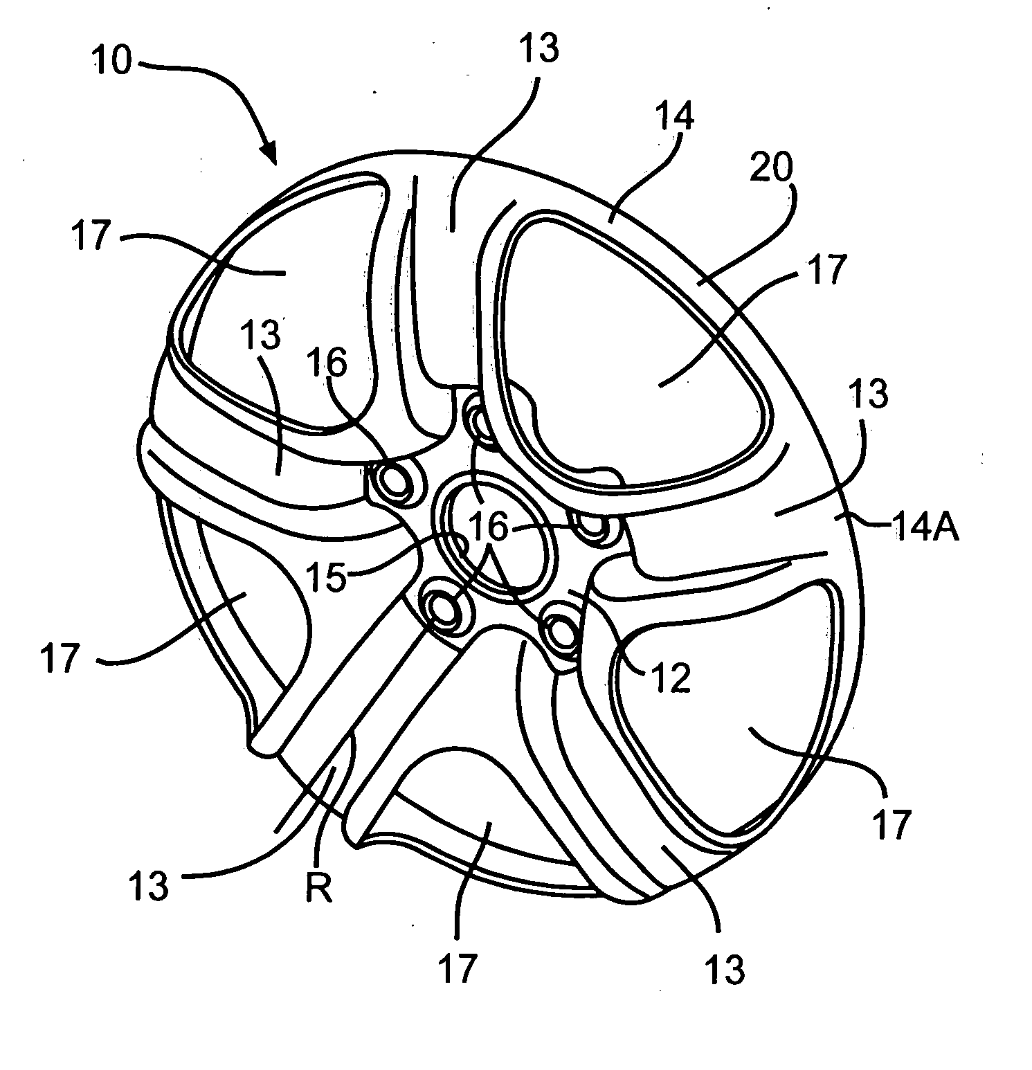
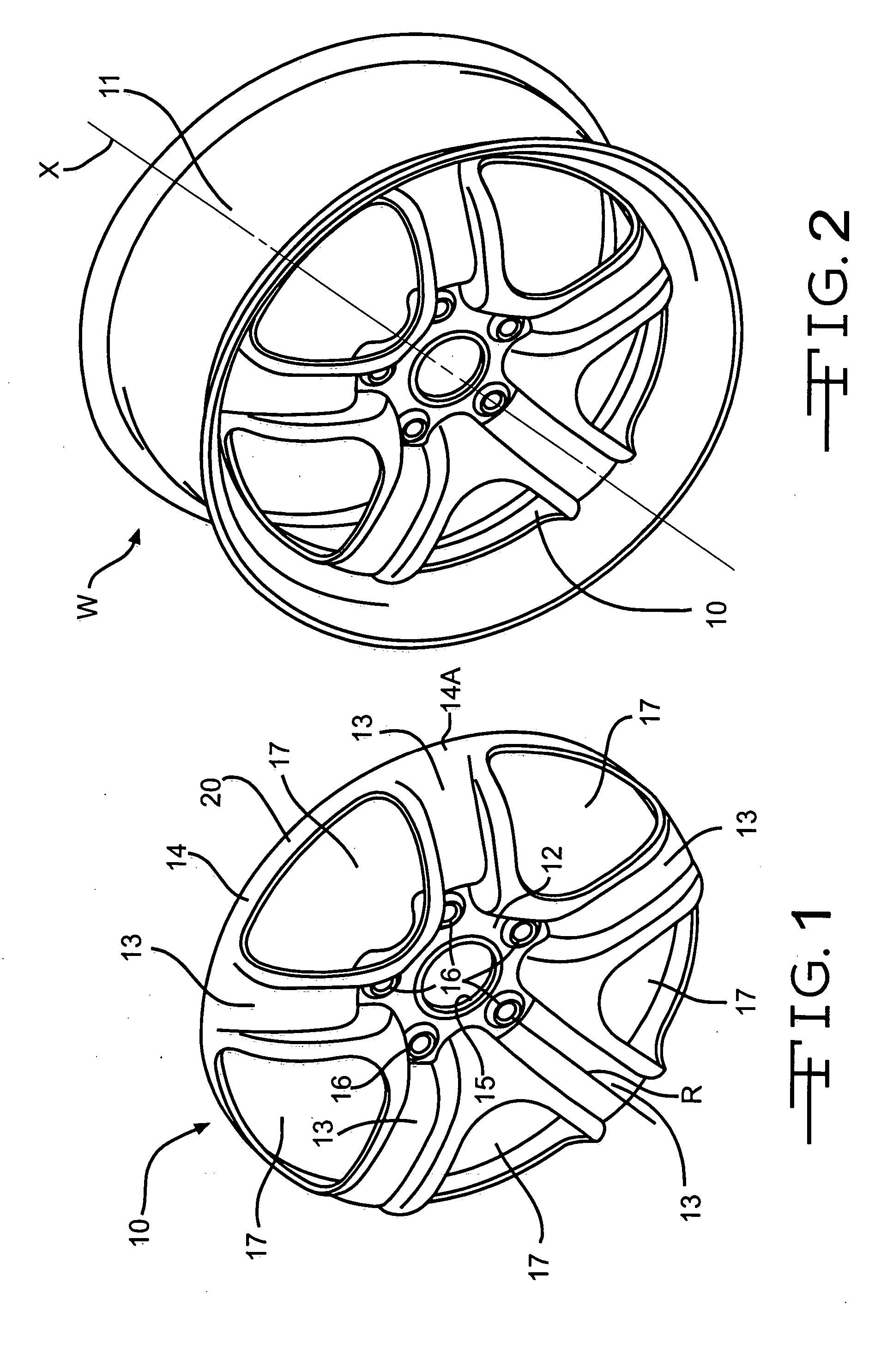
[0031] Referring to FIG. 1, a wheel disc 10 having the shape shown is to be made from flat stock using cold stamping. After it is made, disc 10 may be welded, riveted or otherwise suitably secured to a suitable rim 11, such as shown in FIG. 2, to produce a wheel W having a wheel or wheel disc axis X. Wheel rim 11 is fabricated from a suitable material, such as for example, steel, aluminum or alloys thereof, magnesium, or titanium.

[0032] Wheel disc 10 is fabricated or otherwise formed from a suitable material having the ductility necessary for cold working, such as for example, steel, aluminum or alloys thereof, steel, magnesium, or titanium. Wheel disc 10 includes a generally centrally located wheel mounting surface or contour 12, a plurality of outwardly extending unitary spokes 13, and an outer annular rim connecting band or flange 14. In the illustrated embodiment, disc 10 includes five of such unitary spokes 13 which are integral with the wheel mounting surface 12 and outer ban...


PUM

PropertyMeasurementUnit
angular sizeaaaaaaaaaa
cylindrical shapeaaaaaaaaaa
sizeaaaaaaaaaa

Abstract

A method of forming a wheel disc starts with a flat blank. A plurality of windows are formed in the wheel disc, wherein each window has a respective outer edge proximate with a continuous outer band around a periphery of the wheel disc. The windows define a plurality of spokes between adjacent windows, and the angular size of each of the windows along the outer band is preferably greater than the angular size of each of the spokes. The outer band is partially closed toward a cylindrical shape by engaging a cam die against at least a portion of the outer band. The outer band is substantially fully closed into a cylindrical shape by axially wiping the outer band using a cylindrical die. The intermediate camming operation achieves the desired final shape after wiping without introducing stresses that would weaken or distort the wheel disc.

Description

CROSS REFERENCE TO RELATED APPLICATIONS [0001] The present application is related to co-pending U.S. application Ser. No. 10 / 836,828 and co-pending U.S. application Ser. No. (Attorney Docket 1-27067).BACKGROUND OF THE INVENTION [0002] The present invention relates to vehicle wheels and, more specifically, to an improved method for producing a wheel disc adapted for use in such a vehicle wheel. [0003] One type of conventional fabricated vehicle wheel comprises a two-piece construction having an inner disc and an outer rim. The disc includes an inner wheel mounting portion and an outer annular portion. The wheel mounting portion defines an inboard mounting surface and includes a center pilot or hub hole, and a plurality of lug receiving holes formed therethrough for mounting the wheel to an axle of the vehicle. The rim is fabricated from steel, aluminum, or other alloys, and includes an inboard tire bead seat retaining flange, an inboard tire bead seat, an axially extending well, an o...

Claims


Application Information

Patent Timeline
Patent Type & Authority Applications(United States)
IPC IPC(8): B21D53/26
CPCB21D53/265Y10T29/49503Y10T29/49504Y10T29/49529Y10T29/49492Y10T29/49501Y10T29/49506Y10T29/49496B21D53/26
Inventor COLEMAN, ALANCZARNIECKI, TOMFOWLER, BILL
Owner HAYES LEMMERZ INT
Why Eureka
Try Eureka