Impact power tool

Inactive Publication Date: 2007-08-02
MAKITA CORP
View PDF12 Cites 17 Cited by
  • Summary
  • Abstract
  • Description
  • Claims
  • Application Information

AI Technical Summary

Benefits of technology

[0005]Accordingly, it is an object of the invention to provide an improved technique lessening a

Problems solved by technology

Thus, while two different properties are required to the kno rubber ring, it is difficult

Method used


Image

  • Impact power tool
  • Impact power tool
  • Impact power tool

Examples


first embodiment

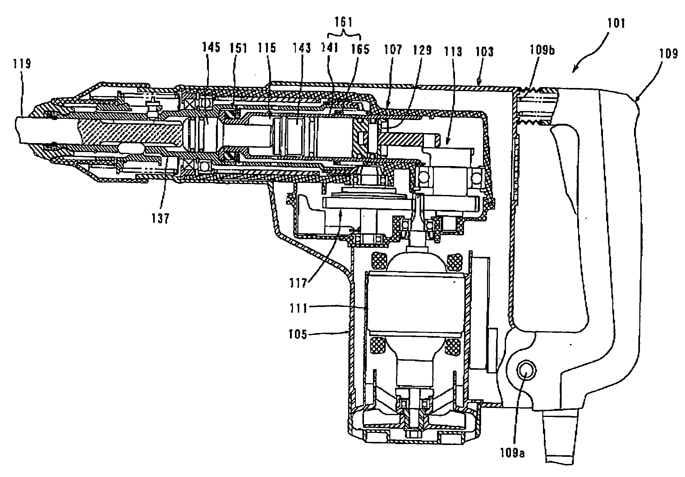
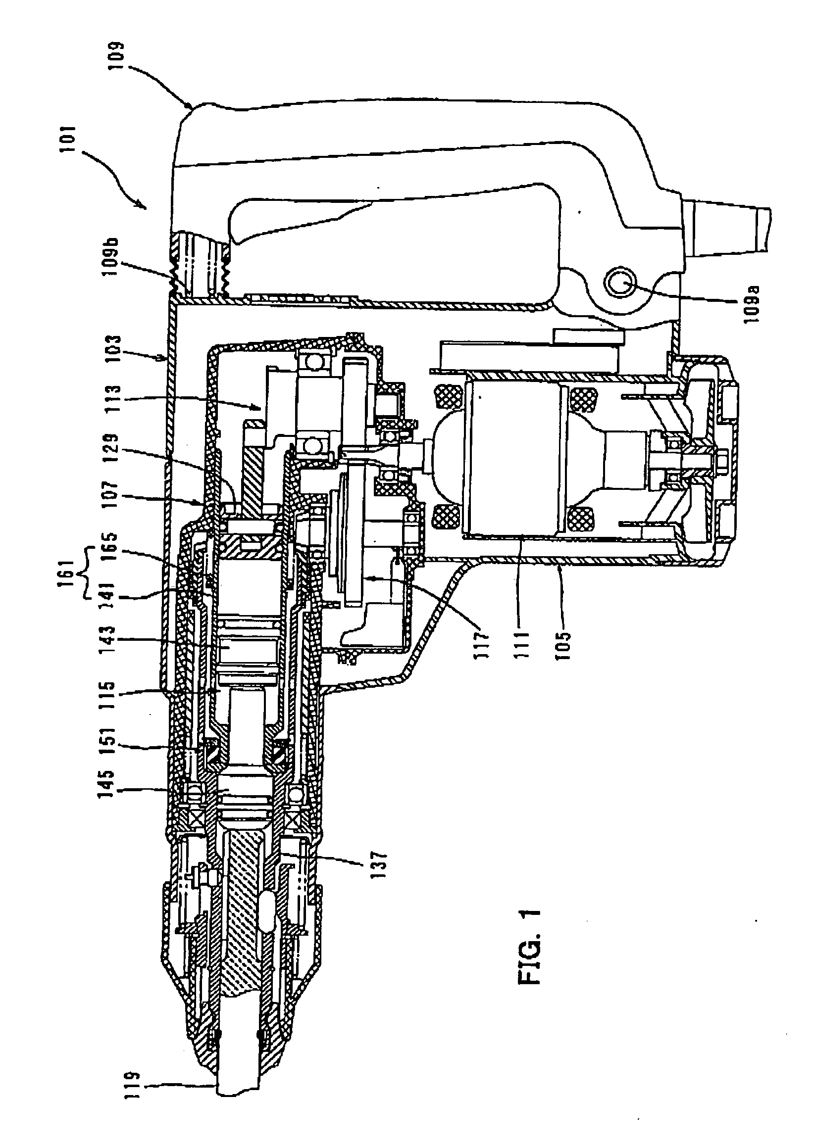
[0030]A first embodiment of the present invention will now be described with referenc FIGS. 1 to 3. FIG. 1 is a sectional side view showing an entire electric hammer drill 101 a representative embodiment of the impact power tool according to the present invention, un loaded conditions in which a hammer bit is pressed against a workpiece. As shown in FIG. 1, hammer drill 101 includes a body 103, a hammer bit 119 detachably coupled to the tip end reg (on the left side as viewed in FIG. 1) of the body 103 via a tool holder 137, and a handgrip 1091 is held by a user and connected to the rear end region of the body 103 on the side opposite hammer bit 119. The body 103 is a feature that corresponds to the “tool body” according to present invention. The hammer bit 119 is held by the hollow tool holder 137 such that it is allow to reciprocate with respect to the tool holder 137 in its axial direction and prevented from rotat with respect to the tool holder 137 in its circumferential directi...

second embodiment

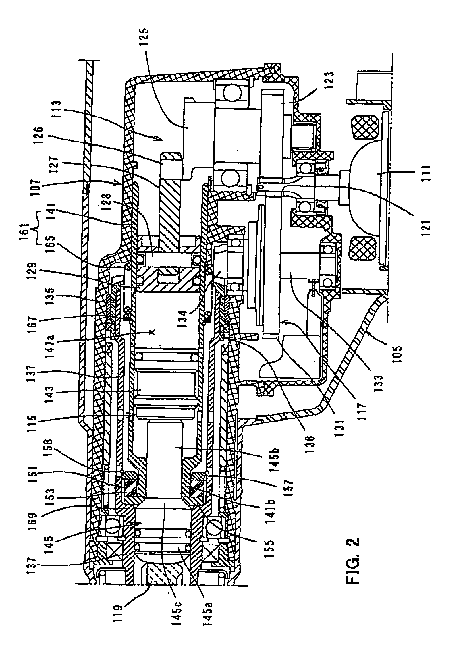
[0050]Now, a second embodiment of the present invention will be described with reference FIGS. 4 to 6. FIG. 4 shows the hammer drill under loaded conditions in which the hammer bit is pressed against the workpiece. FIG. 5 shows the hammer drill during operation of the imp damper. FIG. 6 is a partially enlarged view of FIG. 4. In this embodiment, the cylinder forming the weight of the impact damper 161 is separated into two parts, i.e. a cylinder body 1 for housing the piston 129 and the striker 143 and the front small-diameter cylindrical port 141b which contacts the front metal washer 155 of the positioning member 151. In the o points, it has the same construction as the first embodiment. Components or elements in second embodiment which are substantially identical to those in the first embodiment are gi like numerals as in the first embodiment and will not be described or only briefly described.

[0051]The front end portion of the cylinder body 141c is loosely fitted into the rear e...

third embodiment

[0055]Third embodiment of the present invention will be described with reference to FIG. to 9. FIG. 7 shows the hammer drill under loaded conditions in which the hammer bit 11 pressed against the workpiece. FIG. 8 shows the hammer drill during operation of the im damper. FIG. 9 is a partially enlarged view of FIG. 7. In this embodiment, the impact damper is comprised of existing parts of the hammer drill 101, i.e. the hard metal tool holder 137 an compression coil spring 165 that biases the tool holder 137 toward the impact bolt 145 (forw In the other points, it has the same construction as the first embodiment. Components or ele in the third embodiment which are substantially identical to those in the first embodiment given like numerals as in the first embodiment and will not be described or only briefly descri Further, in this embodiment, the cylinder 141 does not have the front small-diameter cylind portion 141b (see FIG. 2) and is fixedly mounted to the gear housing 107.

[0056]I...


PUM

PropertyMeasurementUnit
Weightaaaaaaaaaa
Forceaaaaaaaaaa
Elasticityaaaaaaaaaa

Abstract

An object of the invention is to provide an improved technique for lessening an imp force caused by rebound of a tool bit after its striking movement in an impact power tool. representative impact power tool comprises a tool body, a hammer actuating member, a holder, a driving mechanism, a weight placed in contact with the hammer actuating member move rearward by a reaction force transmitted from the hammer actuating member when hammer actuating member performs a hammering operation on the workpiece and an ela element elastically deformed when the weight moves rearward in the tool body to push the ela element such that the elastic element absorbs the reaction force transmitted to the weight. weight is defined one or both of the cylinder and the tool holder.

Description

BACKGROUND OF THE INVENTION[0001]1. Field of the Invention[0002]The present invention relates to an impact power tool for performing a linear hammer operation on a workpiece, and more particularly to a technique for cushioning a reaction fo received from the workpiece during hammering operation.[0003]2. Description of the Related Art[0004]Japanese non-examined laid-open Patent Publication No. 8-318342 discloses technique for cushioning an impact force caused by rebound of a tool bit after its strik movement in a hammer drill. In the known hammer drill, a rubber ring is disposed between axial end surface of a cylinder and an impact bolt. The rubber ring has a function of cushion the impact force caused by rebound of the tool bit and positioning the hammer drill during hammering operation. It is advantageous to make the rubber ring soft in order to absorb rebound of the tool bit. On the contrary, it is advantageous to make the rubber ring hard in order improve the positioning accuracy...

Claims


Application Information

Patent Timeline
IPC IPC(8): B23B45/16
CPCB25D16/00B25D17/06B25D17/24B25D17/245B25D2211/003B25D2211/068B25D2250/391B25D2217/0019B25D2217/0084B25D2217/0092B25D2250/035B25D2250/245B25D2250/371B25D2216/0023
Inventor AOKI, YONOSUKE
Owner MAKITA CORP
Why Eureka
Try Eureka