Machine with an improved bearing lubrication

a technology of bearing lubrication and machine, which is applied in the direction of bearing cooling, machines/engines, sliding contact bearings, etc., can solve the problems of premature wear, heat dissipation of the rotor concerned, and heat generation of the rotor, so as to prolong the life of the bearing, reduce heat flow, and reduce the loss of bearings.

Active Publication Date: 2007-08-02
ATLAS COPCO AIRPOWER NV
View PDF14 Cites 39 Cited by
  • Summary
  • Abstract
  • Description
  • Claims
  • Application Information

AI Technical Summary

Benefits of technology

[0022] An advantage of the invention is that no excessive amount of oil must be sent to the bearings in order to cool the bearings, as a result of which this amount of oil can be optimized for sufficient lubricating film to be built up, such that the bearing losses are strongly reduced.
[0023] Another advantage is that, thanks to the direct injection of a cooling agent on the shaft, the heat flow of the rotor to the bearing is interrupted, as a result of which a reduced heat flow flows to the bearing and as a result of which also the life of the bearing is extended, since the viscosity of the oil is not affected by the temperature of the bearing.
[0024] An additional advantage of the lower temperature of the bearing is that a standard bearing cage can be used for the bearings, as a result of which the cost price of the bearings can be lowered.
[0025] Still another advantage of such a machine according to the invention is that the lubricating oil also serves as a cooling agent for the shaft, which allows to make the construction of the machine compact, relatively cheap and simple as it does not require the presence of separate circuits.
[0026] According to a preferred characteristic of the invention, the rotor shaft is provided, opposite to the cooling channels, with one or several grooves.
[0027] This offers the major advantage that the contact surface between the cooling agent and the shaft increases, which considerably improves the cooling of the shaft.

Problems solved by technology

A problem which occurs, for example in case of screw compressors, is that, due to the heat development of the compression, the rotor is heated, and that this heat of the rotor concerned, is dissipated via the rotor shaft and the bearings of this rotor shaft to the environment, as a result of which the bearings are heated.
Such a heating of the bearings leads to premature wear, more particularly of the roller elements and of the bearing rings of the bearings, as the warming up has a negative influence on the viscosity of the lubricating oil, and this viscosity may be insufficient to build up the lubricating film in a sufficient manner.
Said excessive use of oil is disadvantageous however, in that there are additional, unwanted bearing losses, as the oil which is present in the bearing is turned over, and which bearing losses become in particular apparent at high rotational speeds, leading to a lower efficiency of the bearing as such, and consequently of the machine as a whole.
Another disadvantage of the bearings being warmed up, is that the bearing cage must usually be made of a special material which resists high temperatures, which is expensive.
When ball bearings with an angular contact are used, the problem of the bearing losses is further increased as a result of the pumping operation of this type of bearing.
A disadvantage of such known machines is that they are complex and require completely separate circuits for cooling the shaft and lubricating the bearing.
Also, the air or gas cooling will be insufficient for cooling the shaft and for realizing a proper functioning and a long life of the machine.
The excessive lubrication of the bearings leads to additional stilling losses, and the cooling oil is moreover heated in this bearing, as a result of which the shaft, which is irrigated by said oil, will be cooled less efficiently.
However, these additional cooling methods are not efficient and require additional measures, in this case in the form of compressed air injection, in order to avoid that oil ends up in the space between the rotor and the stator.

Method used


Image

  • Machine with an improved bearing lubrication
  • Machine with an improved bearing lubrication
  • Machine with an improved bearing lubrication

Examples


Embodiment Construction

)

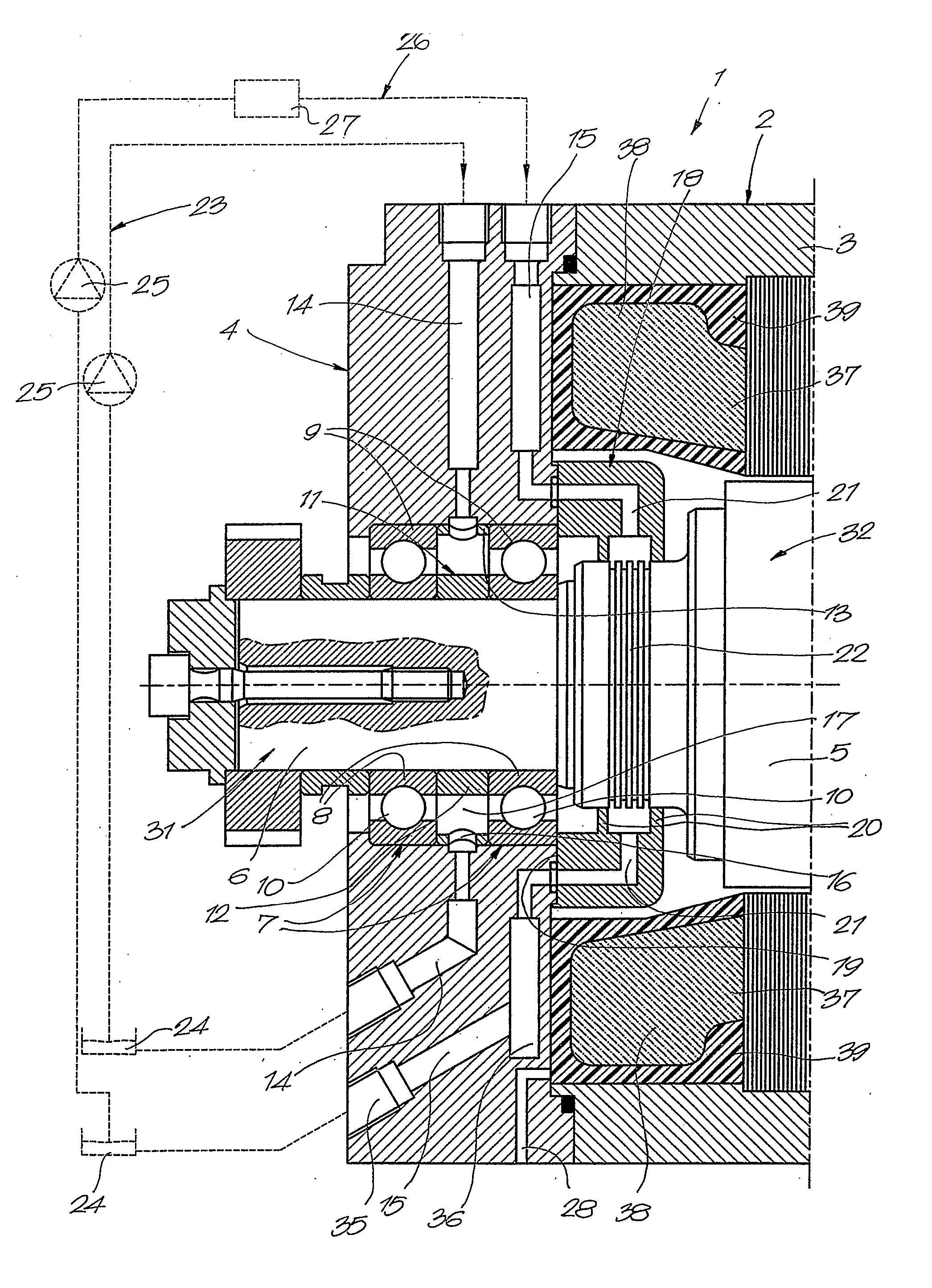
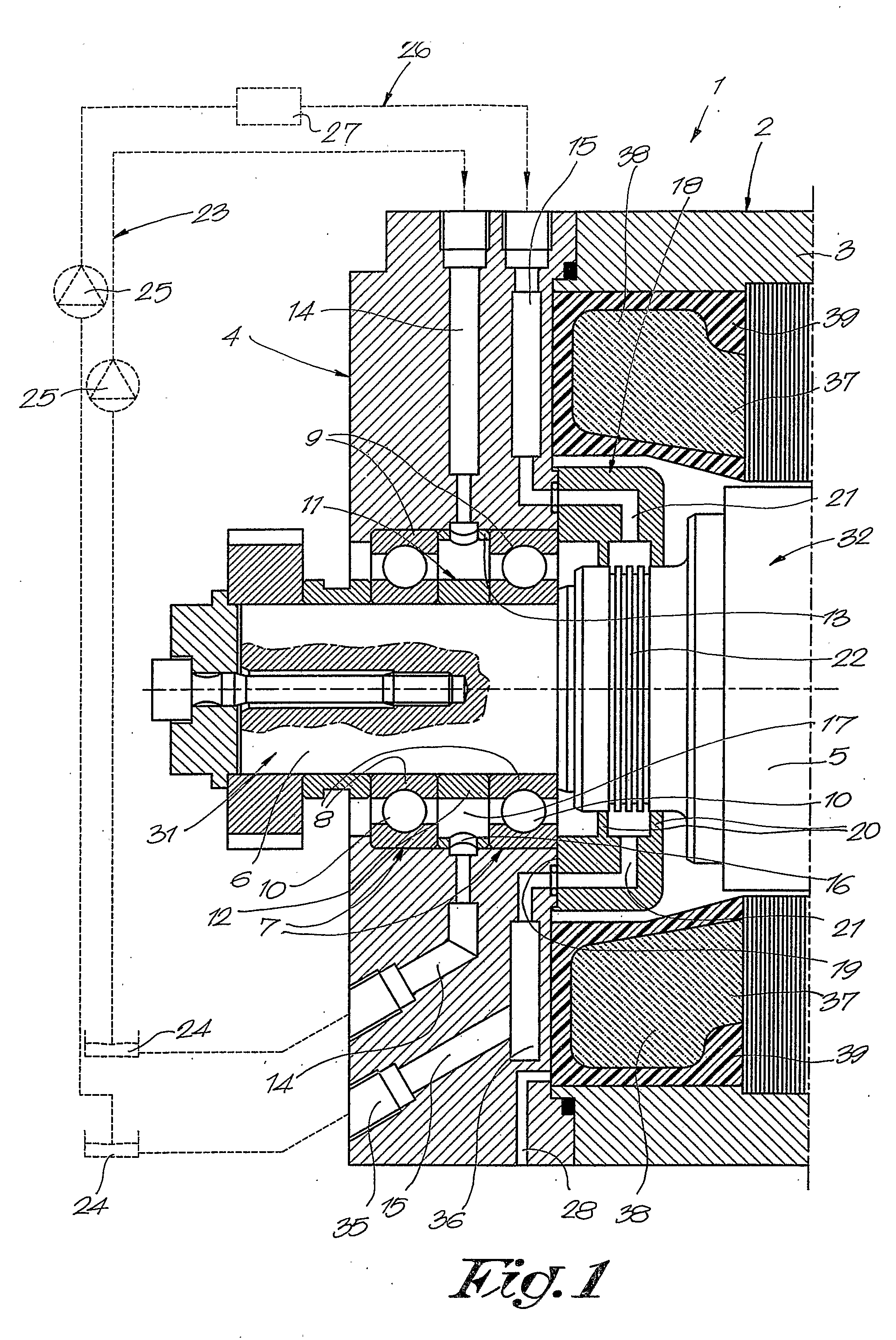
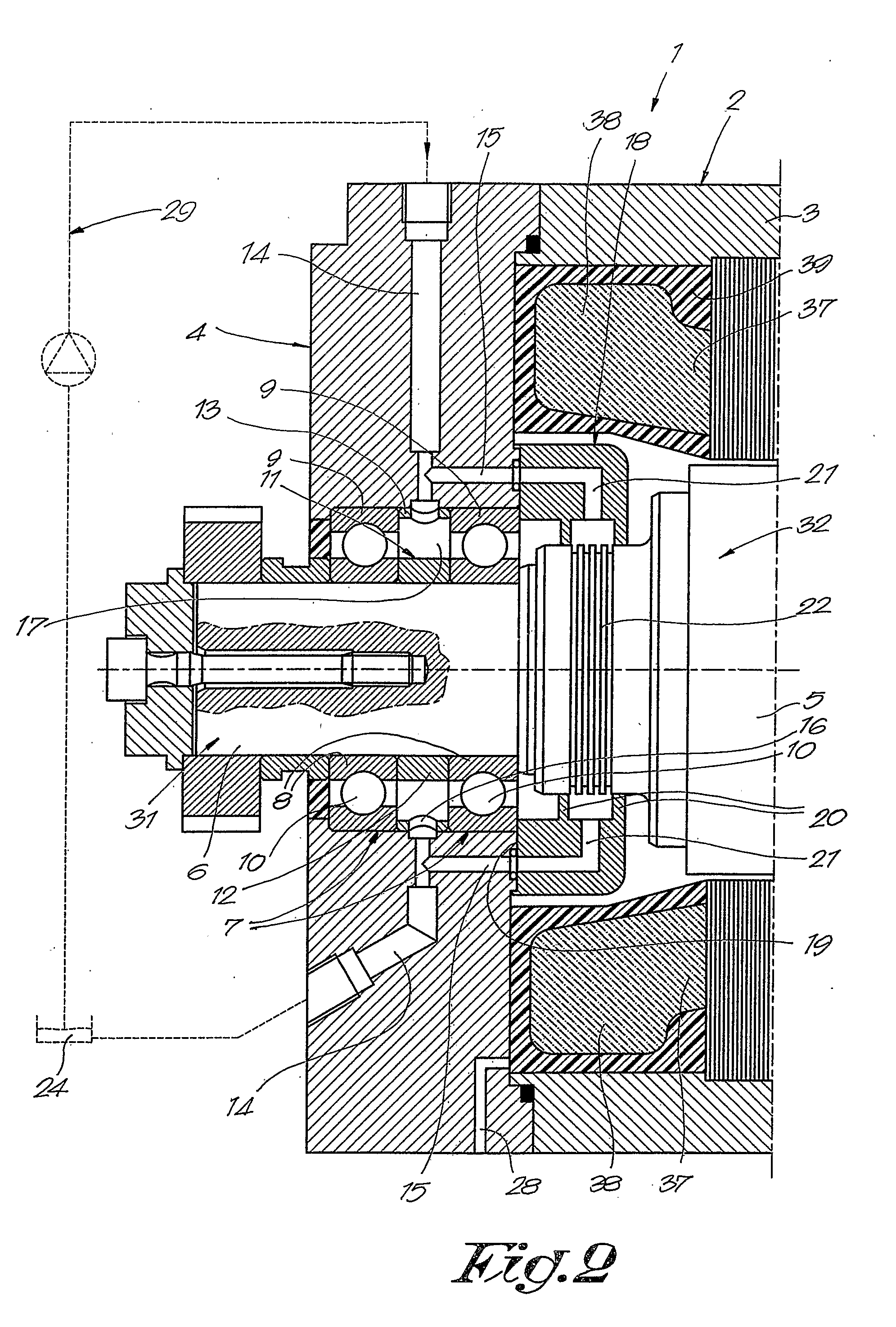
[0037]FIG. 1 represents a part of an electric motor 1, more particularly of an axial end of such a motor 1, which mainly consists of a housing 2 with a jacket 3 which is sealed at the represented far end by means of a bearing cap 4.

[0038] In the above-mentioned housing 2 is provided a rotor 5, provided on a shaft 6, which shaft 6 is provided in the above-mentioned housing 2 in a rotating manner by means of bearings 7, which are provided at the represented far end, in the above-mentioned bearing cap 4.

[0039] Each of the bearings 7 in this case consists of an inner ring 8 and an outer ring 9, in between which are situated roller elements 10, in this case balls.

[0040] Between the bearings 7 is provided a spacer sleeve 11 which consists of two concentric rings 12 and 13, the inner ring 12 of which is provided on the shaft 6 and the outer ring 13 of which is provided in the bearing cap 4.

[0041] In the bearing cap 4 are also provided lubrication ducts 14 and separate cooling channels...


PUM


Abstract

Machine with an improved bearing lubrication, including a housing (2) and a rotor (5) which is provided on a shaft (6), provided in a rotatable manner in the above-mentioned housing (2) by means of oil-lubricated bearings (7), wherein, inside the housing (2), lubrication ducts (14) to supply and discharge oil to and from the bearings (7), and cooling channels (21, 15) to supply and discharge a cooling agent, are provided which cooling channels (21, 15) open opposite to the shaft (6), in a place between the rotor (5) and a bearing (7).

Description

BACKGROUND OF THE INVENTION [0001] A. Field [0002] The present invention concerns a machine with an improved bearing lubrication. [0003] B. Related Art [0004] More particularly, the invention concerns a machine with an improved bearing lubrication, which machine mainly consists of a housing and a rotor which is provided on a shaft, provided in a rotatable manner in the above-mentioned housing by means of oil-lubricated bearings. [0005] Several methods for lubricating such bearings are already known, such as an oil bath lubrication, an oil circulation system, an oil injection lubrication, the oil drop method, an oil mist lubrication and what is called the oil minimum lubrication. [0006] Depending on the application, a specific lubrication method is selected, whereby it is always important to find a balance between sufficient oil being available on the one hand to build up a lubricating film which guarantees that there is no contact between the rolling elements and the bearing rings, ...

Claims


Application Information

Patent Timeline
Patent Type & Authority Applications(United States)
IPC IPC(8): F16C19/00F16C33/66F16C37/00H02K5/173H02K7/08H02K9/19
CPCF16C33/6651F16C33/667F16C33/6674H02K9/19F16C37/007H02K5/1732H02K7/083F16C33/6685F16C2380/26F16C33/6659
Inventor VERHAEGEN, KEN GUSTAAF HELENA
Owner ATLAS COPCO AIRPOWER NV
Why Eureka
Try Eureka