Radial bearing

a radial bearing and bearing seat technology, applied in the direction of sliding contact bearings, mechanical equipment, machines/engines, etc., can solve the problems of unsatisfactory both technically and financially, unsatisfactory fatigue strength of radial bearings, etc., to achieve high viscosity hydraulic means, reduce friction power loss, and reduce friction. the effect of the roller

Active Publication Date: 2007-08-02
SCHAEFFLER TECH AG & CO KG
View PDF7 Cites 15 Cited by
  • Summary
  • Abstract
  • Description
  • Claims
  • Application Information

AI Technical Summary

Benefits of technology

[0013] In an especially advantageous continuation of the invention, it is further provided that for radial bearing of the unbalanced weight shaft, there is at least one roller bearing formed as a needle bearing without an inner ring and preferably as a needle sleeve. In addition to the favorable friction properties of the roller bearing in comparison with a hydrodynamic sliding bearing, which can lead to considerable friction power losses in the drive of the unbalanced weight shaft, especially at low temperatures and/or high viscosity hydraulic means, the advantages of the mass reduction and/or the unbalanced weight increase of the unbalanced weight shaft can be even further expanded by its radial bearing formed as a needle bearing, because the bearing seat included by a needle bearing as a rule can be narrowed more than would be possible in the case of the hydrodynamic sliding bearing based on consideration of a weight-bearing lubricant film. Thus, the use of a needle sleeve, which is known to someone skilled in the art as a component with very small radial installation height with a non-cutting shaped outer ring and a needle collar, permits above all an especially installation space-saving and economical r...

Problems solved by technology

However, for the required width outside of the load zone, this criteria still plays only a subordinate role, because here the bearing seat is subjected to a clearly lower mechanical load and, in individual cases, to no mechanical load at all.
This can produce significant disadvantages to the extent that the bearing seat, which is, for the most part, superior in terms of production, has a mass, which is undesired both technically and financially, and which is also avoidable, outside of the load zone.
Simultaneously, this leads to unnecessarily high processing costs for the bearing seat, which is to be machined with fine precision completely over its constant width, even outside of the load zone.
Such a negative effect would be produced when, due to the narrowing of the bearing seat, a critical bearing seat width is reached, below which a given fatigue strength of the radial bearing is no longer guaranteed.
In this case, a bearing seat of variable width can lead to a mass reduction of t...

Method used


Image

  • Radial bearing
  • Radial bearing
  • Radial bearing

Examples


Embodiment Construction

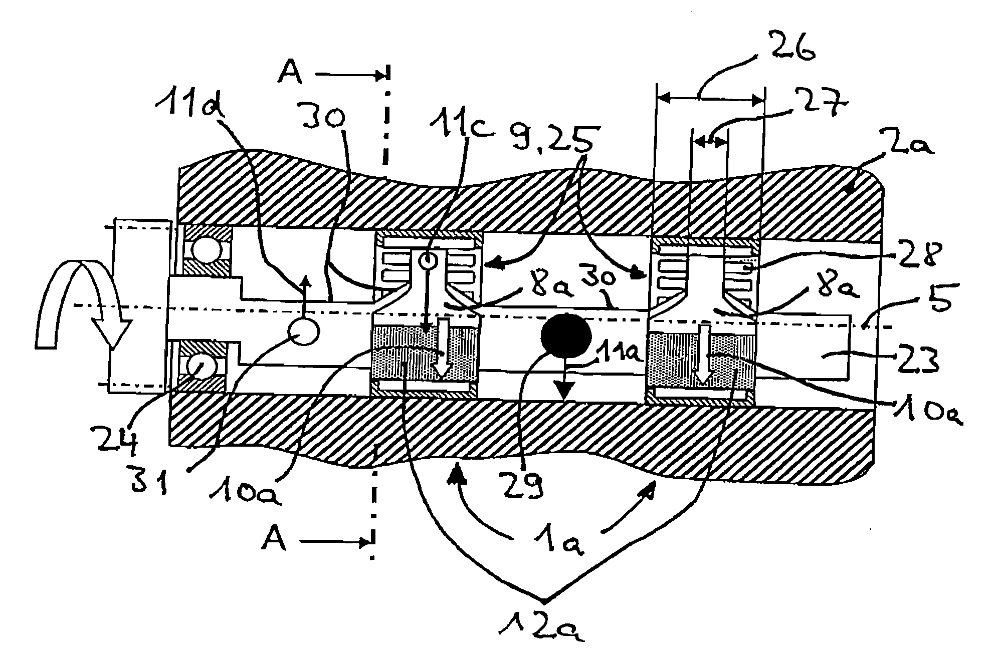
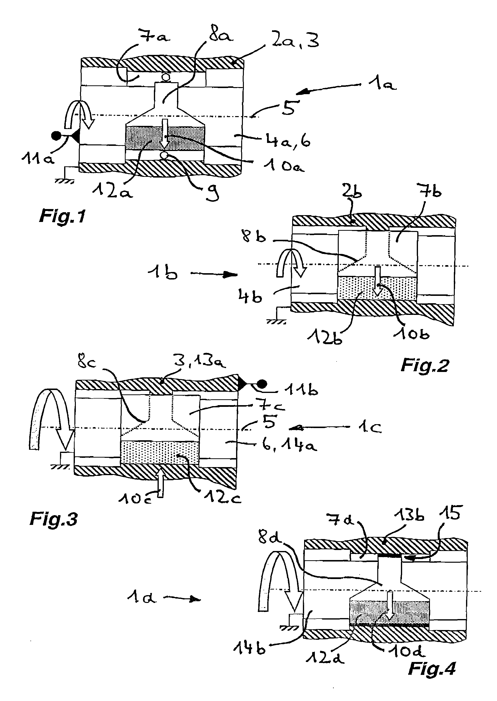
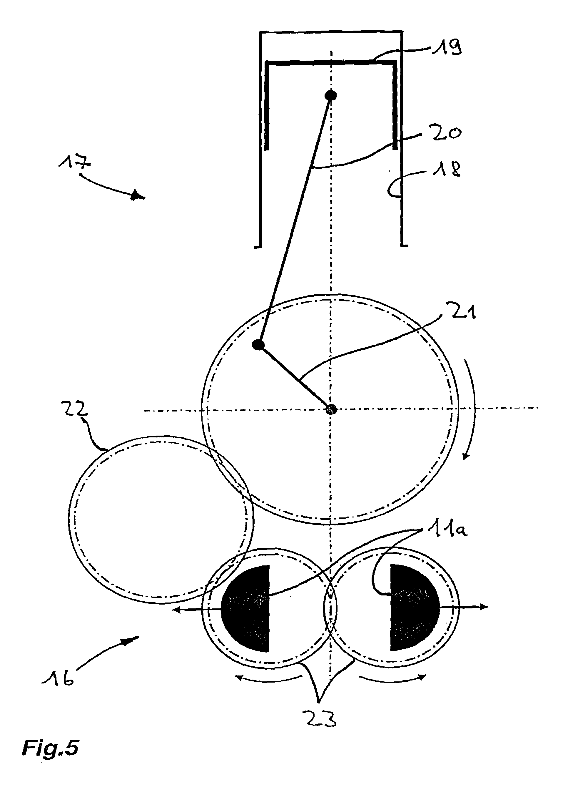
[0023] In FIG. 1, a radial bearing 1a according to the invention for a first load case is disclosed. Shown is an outer part 3, which is formed as a housing 2a and in which the inner part 6 formed as a shaft 4a and rotating about a longitudinal axis 5 is mounted radially. In the illustrated embodiment, a roller bearing 9 is located between a bearing seat 7a formed in the housing 2a and a bearing seat 8a formed on the shaft 4a, which can also be used as the radial bearing 1b, 1c, 1d according to FIGS. 2-4 as a bearing means. A radial load 10a rotating with the shaft 4a leads to a peripheral load on the bearing seat 7a of the housing 2a due to an unbalanced weight 11a arranged on the shaft 4a, while the radial load 10a is generally stationary relative to the bearing seat 8a of the shaft 4a and a load zone 12a (shown with shading) constructed on the shaft. While the bearing seat 7a of the housing 2a is constructed rotationally symmetric due to the peripheral load, the bearing seat 8a of...


PUM


Abstract

A radial bearing (1a, 1b, 1c, 1d), especially a roller bearing (9) comprising an outer part (3) opposite an inner part (6), which rotate relative to each other about a common longitudinal axis (5) is provided, wherein the radial bearing (1a, 1b, 1c, 1d) includes a bearing seat (8a, 8b, 8c, 8d), which is formed in the outer part (3) or on the inner part (6) and which is generally stationary relative to a radial load (10a, 10b, 10c, 10d) acting on the bearing seat (8a, 8b, 8c, 8d) in a load zone (12a, 12b, 12c, 12d). The bearing seat (8a, 8b, 8c, 8d) features a variable width over its extent in a direction of the longitudinal axis (5), such that, starting from the load zone (12a, 12b, 12c, 12d), the bearing seat (8a, 8b, 8c, 8d) is significantly narrowed outside of the load zone (12a, 12b, 12c, 12d).

Description

FIELD OF THE INVENTION [0001] The invention relates to a radial bearing, especially a roller bearing, comprising an outer part opposite an inner part, wherein the outer part and the inner part rotate relative to each other about a common longitudinal axis, wherein the radial bearing comprises a bearing seat, which is formed in the outer part or on the inner part and which is generally stationary relative to a radial load acting on the bearing seat in a load zone. BACKGROUND OF THE INVENTION [0002] In principle, such a load case of the radial bearing is known in the state of the art and, in the case of the roller bearing, under the designation of the so-called point load, at which the radial load is generally stationary as a function of the movement relationships relative to the inner ring or the outer ring of the roller bearing. In contrast, the so-called peripheral load involves a load case, in which the radial load rotates relative to the inner ring or to the outer ring of the rol...

Claims


Application Information

Patent Timeline
IPC IPC(8): F16C19/24
CPCF16C17/02F16C19/06F16C33/585F16F15/267F16C33/581F16C19/46F16C2361/53F16C25/06F16C19/00F16C19/02
Inventor TISCH, SIEGFRIEDSOLFRANK, PETER
Owner SCHAEFFLER TECH AG & CO KG
Why Eureka
Try Eureka