
Printing image frames corresponding to motion pictures

a technology of image frames and motion pictures, applied in the field of printing image frames, can solve the problems of inability to create images, limitations in the speed of scanners, inherent limitations of the maturity used to print images onto motion picture photosensitive mediums, etc., and achieve the effect of improving performan

Inactive Publication Date: 2007-08-09
EASTMAN KODAK CO
View PDF21 Cites 44 Cited by
  • Summary
  • Abstract
  • Description
  • Claims
  • Application Information

AI Technical Summary

Problems solved by technology

Some of these technologies in their current level of maturity used to print images onto motion picture photosensitive medium are known to have inherent limitations.
CRT systems such as that described in U.S. Pat. No. 4,754,334 are slow, relatively large and generally do not have the capability to create images that make use of the full exposure range of the motion picture film because of the low radiance output of the CRT.
The limitations in such systems as described in U.S. Pat. No. 5,296,958 are due primarily to the limitations in speed of the scanner.
The raster scan system is also relatively complex in its construction.
It should be noted that no one has built such a fast system because of the cost and complexity involved.
Electron beam systems are complex and the need to use special film types is a hindrance.
It is not practical to simply scale up these systems in order to gain speed.
In order to print faster, the scanners will have to operate at higher speeds but there are practical limitations relative to speed, the number of scanner mirrors, and the diameter of the scanner disk and cost.
It is possible to go faster but such an effort would result in added complexity, such as placing the scanner in a vacuum chamber to protect it and reduce drag.
The power density of the writing spot may have to increase and the exposure time may have to decrease which could lead to reciprocity failures in the photosensitive medium.
The color content and peak wavelengths that the human eye would be optimally responsive to is not necessarily optimal for specific types of photosensitive medias.
Even more significant are differences in resolution requirements.
The current available resolution using digital micromirror device (DMD), as shown in U.S. Pat. Nos. 5,061,049 and 5,461,411 is not sufficient for the printing needs of the motion picture film industry and there is no clear technology path to increase the resolution.
DMDs are expensive and not easily scaleable to higher resolution.
While such a method offers several advantages in ease of optical design for printing, there are several drawbacks to the use of conventional transmissive LCD technology.
Transmissive LCD modulators generally have reduced aperture ratios and the use of transmissive field-effect-transistors (TFT) on glass technology does not promote the pixel-to-pixel uniformity desired in many printing applications, especially that required in high resolution motion imaging.
In order to provide high resolution, the transmissive LCD modulator's footprint would have to be several inches in both dimensions, which would make the design of a practical output projection lens unreasonable in both cost and size.
Transmissive LCD modulators are constrained to either low resolution and / or small images unsuitable for use in motion picture industry applications.
The problem with these devices in the motion picture printer application is that to obtain the needed high resolutions of 6 to 12 micrometer pixel pitch on 35 mm motion picture film, the LCD modulator would be relatively large.
The design of the output projection lens would be costly and complex.
Convergence of the three colors in a pixel would also be potentially a problem creating apparent and unacceptable color shifts and other artifacts in the image.
While OLED devices have been suggested for use in digital printers for photographic media in U.S. Pat. Nos. 5,482,896 and 5,530,269, US2002 / 0118270, and WO 03 / 092259, such disclosures do not overcome all performance problems associated with the use of OLED devices in such application.
Such a wide divergence angle would be a problem in the design of a film printer system, as a divergence angle of approximately 15 degrees would be more preferred from an optical collection point of view.
A broadband light source can easily cause cross talk between colors records on photographic film and produce images that are unacceptable.
For example, broadband light in the green color record can expose the blue or red color record on film, this unwanted exposure will add to the normal exposure for the respective color channels and create false or contaminated color images.

Method used


Image

  • Printing image frames corresponding to motion pictures
  • Printing image frames corresponding to motion pictures
  • Printing image frames corresponding to motion pictures

Examples


Embodiment Construction

[0032] The present invention is particularly suited for printing frames of either monochromatic (e.g., black and white) or full color motion pictures images. Digital image files for such motion pictures images can either be generated by a digital camera, scanned from images recorded on a photographic medium, or can be computer generated digital images.

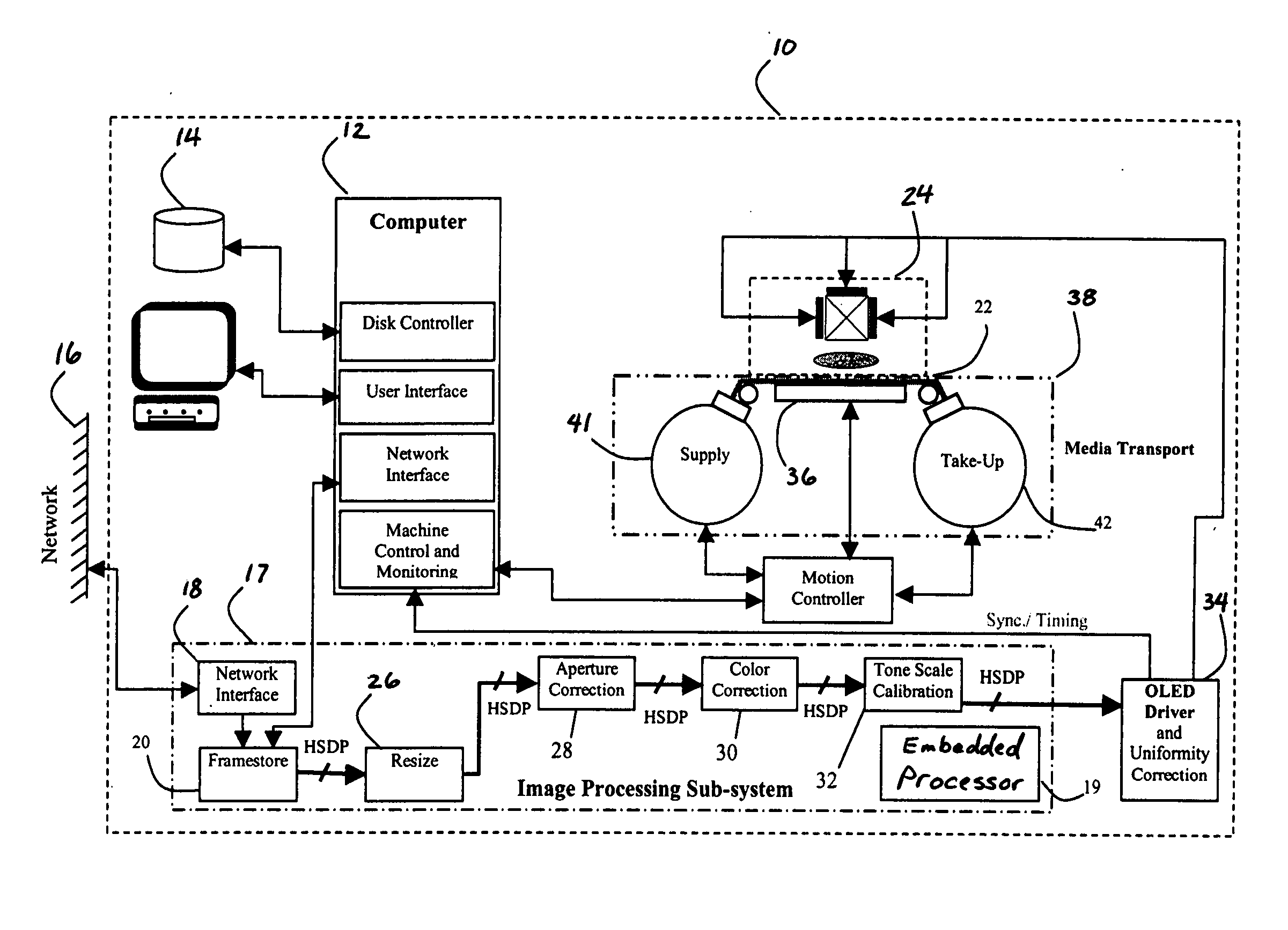
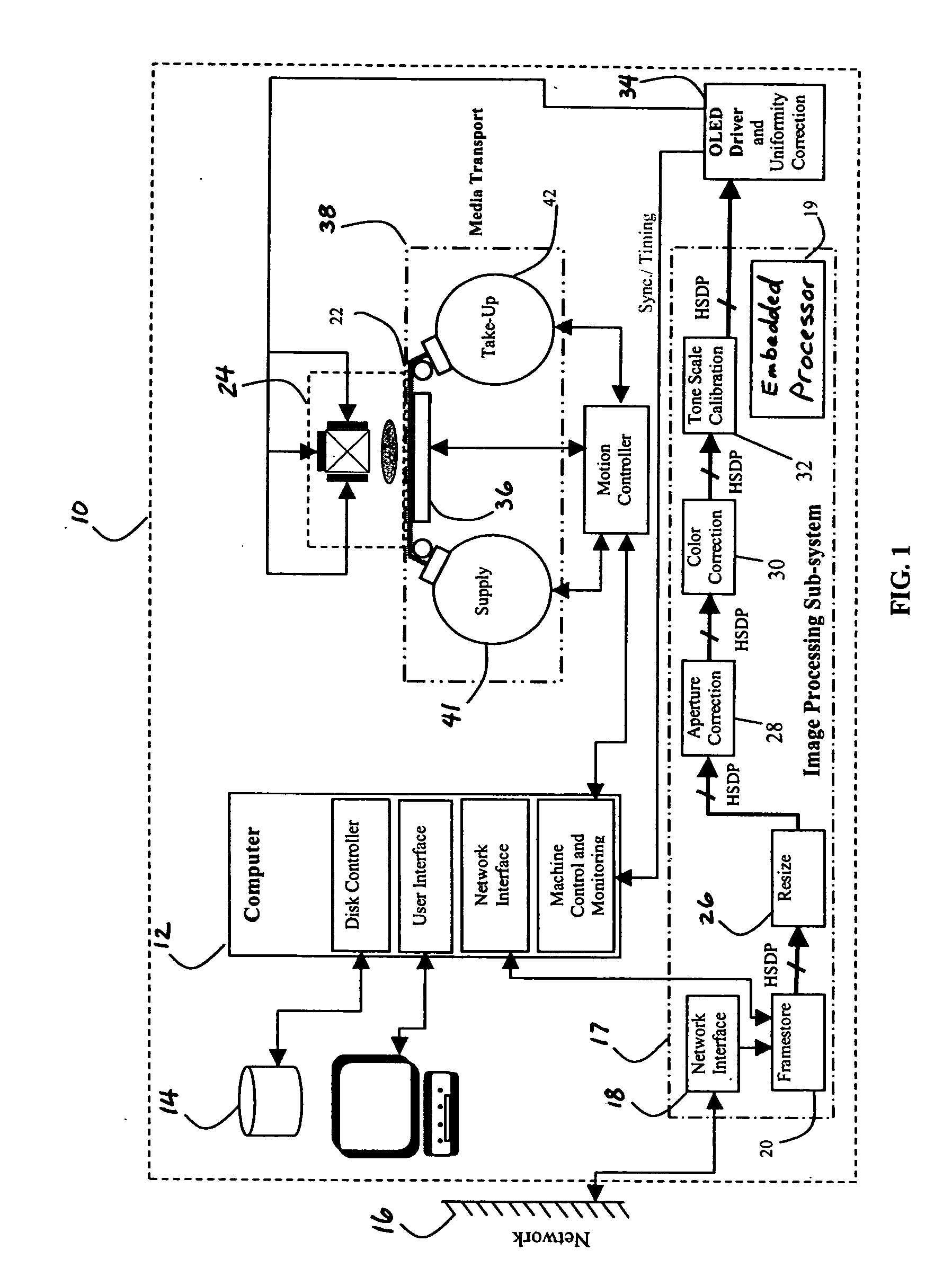
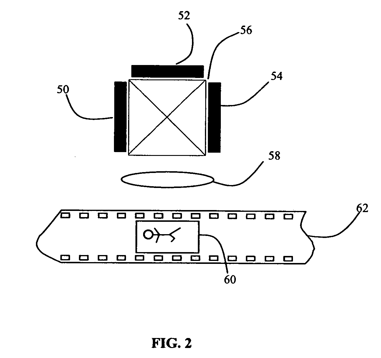
[0033] Organic Light Emitting Diode (OLED) arrays can be made as a two dimensional monochromatic array of pixels or as a multi-color (e.g., red, green, blue tri-color) side by side pixel array, or even as a tri-color stacked pixel array. The array sizes, pixel pitch and aspect ratios can be made in a variety of resolution and densities. Each pixel site in a tri-color side by side or stacked array is composed of three light emitting diodes of different colors. Each light emitting diode in a tri-pixel site and therefore the entire array can be individual controlled to produce an effect similar to that of a color cathode ray tube in a te...


PUM


Abstract

A method of printing a plurality of image frames from a digital image file of a motion picture sequence to a photosensitive medium comprising one or more light-sensitive recording layers, comprising the steps of: a) providing at least one two-dimensional OLED modulator, wherein the OLED modulator comprises an array of independently activatable microcavity OLED elements, each OLED element defining an optical cavity for reducing the angle of emission of light from the OLED element and tuning the light output of the OLED element to a limited spectral band emmitance range wavelength matched to the spectral sensitivity of a light-sensitive recording layer of the photosensitive medium; b) responding to the digital image file to independently activate the OLED elements in the two-dimensional OLED modulator to provide visual images corresponding to each frame of the motion picture sequence; and c) moving the photosensitive medium past the visual images to illuminate different portions the medium to record the motion picture sequence on the medium.

Description

FIELD OF THE INVENTION [0001] The present invention relates to a method and apparatus for printing image frames from a digital image file of a motion picture sequence. BACKGROUND OF THE INVENTION [0002] Digital images have been printed onto photosensitive medium using systems based on liquid crystal display (LCD), digital micromirror device (DMD), lasers and acoustic optical modulators, cathode ray tubes (CRT) and electron gun as the primary means of modulating the illuminating sources to create the images. Some of these technologies in their current level of maturity used to print images onto motion picture photosensitive medium are known to have inherent limitations. CRT systems such as that described in U.S. Pat. No. 4,754,334 are slow, relatively large and generally do not have the capability to create images that make use of the full exposure range of the motion picture film because of the low radiance output of the CRT. It takes approximately 20 seconds to print a 2000 pixel r...

Claims


Application Information

Patent Timeline
Patent Type & Authority Applications(United States)
IPC IPC(8): B41J2/45
CPCB41J2/45G03B33/00H04N5/87H04N5/765H01L51/5265H10K59/876H10K50/852
Inventor YARID, ROCKWELL N.OEHLBECK, MARTIN E.DRUZYNSKI, RICHARD L.PALUM, RUSSELL J.O'TOOLE, TERRENCE R.
Owner EASTMAN KODAK CO
Learn More