Methods and systems for determining temperature of an object

a technology of temperature and object, applied in the field of temperature sensors, can solve problems such as significant computational requirements

Inactive Publication Date: 2007-08-09
AMPHENOL THERMOMETRICS
View PDF16 Cites 93 Cited by
  • Summary
  • Abstract
  • Description
  • Claims
  • Application Information

AI Technical Summary

Problems solved by technology

However, the relationship between output voltage and temperature is a 4th

Method used


Image

  • Methods and systems for determining temperature of an object
  • Methods and systems for determining temperature of an object
  • Methods and systems for determining temperature of an object

Examples


Embodiment Construction

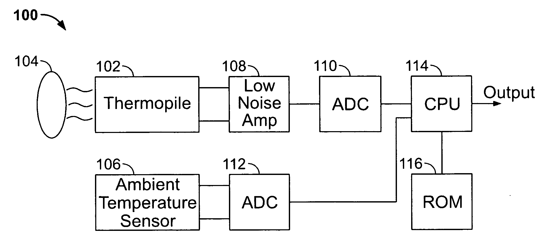
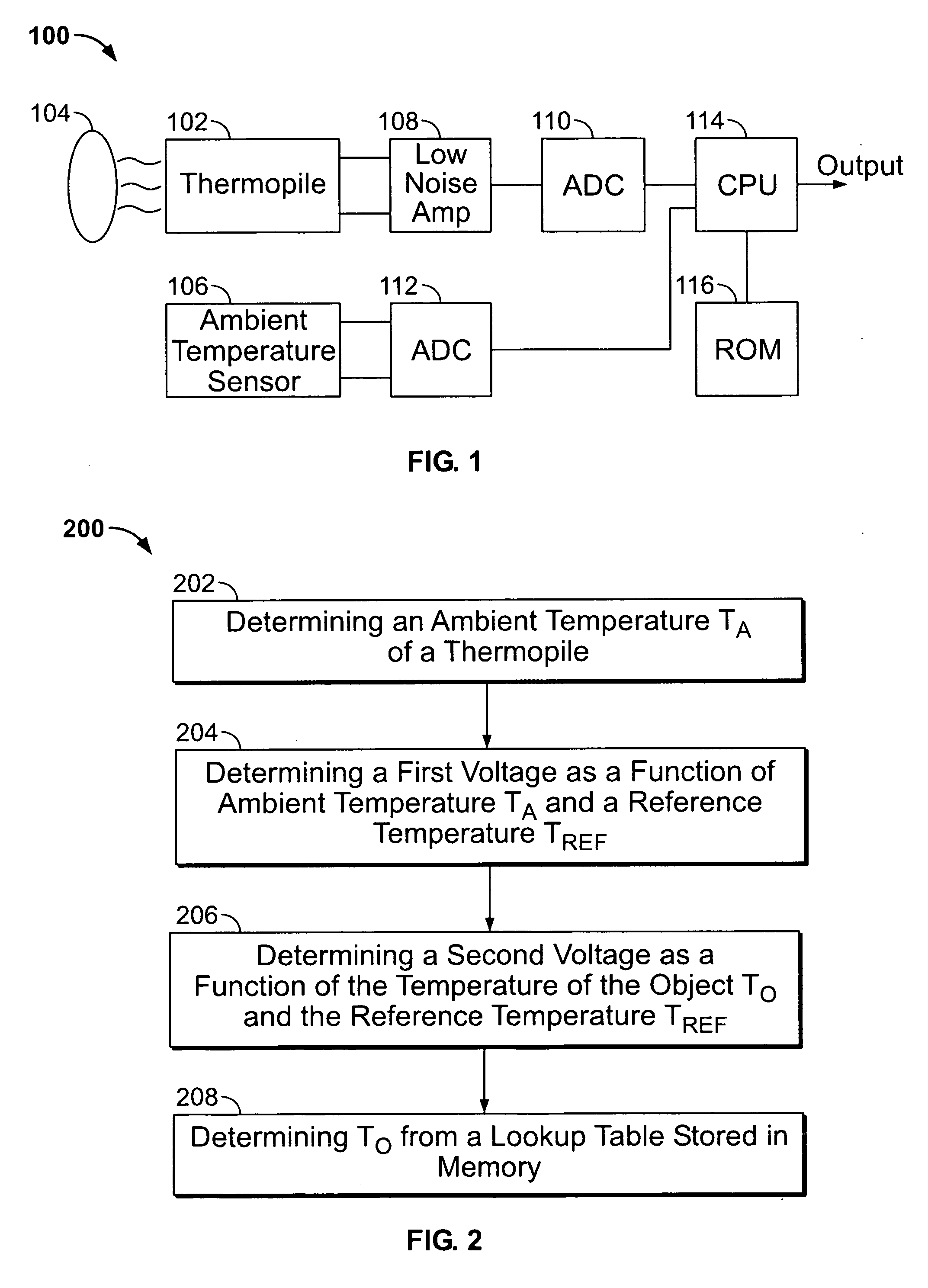
[0011]FIG. 1 is a block diagram of a thermopile sensor system 100 in accordance with an exemplary embodiment of the present invention. System 100 includes a thermopile detector 102 configured to receive infrared radiation that is correlative to the temperature TO of a remote object 104. Thermopile detector 102 provides a low level analog output varying with both object temperature TO and ambient temperature TA. An ambient temperature sensor 106, used to measure the ambient temperature of the thermopile is located proximate to thermopile detector 102. In the exemplary embodiment, ambient temperature sensor 106 is a thermistor. In various alternative embodiments, ambient temperature sensor 106 is a silicon temperature sensor or resistance temperature detector (RTD).

[0012] Thermopile detector 102 is communicatively coupled to a low noise amplifier 108 and to analog-to-digital converter 110. Ambient temperature sensor 106 is communicatively coupled to analog-to-digital converter 112. T...


PUM


Abstract

Methods and systems for detecting a temperature TO of a remote object are provided. The method includes storing in memory, a lookup table relating an output voltage of an infrared sensor to a temperature sensed by the infrared sensor V(TO, TA), determining a temperature sensor voltage output corresponding to a temperature TA proximate the infrared sensor, determining a first voltage as a function of the temperature TA proximate the infrared sensor and a reference temperature TREF, V(TA,TREF), determining a second voltage as a function of the temperature of the object TO and the reference temperature TREF, V(TO,TREF) by combining the determined temperature sensor voltage output and the first voltage, and determining a temperature of the object TO from the lookup table using the second voltage.

Description

BACKGROUND OF THE INVENTION [0001] This invention relates generally to temperature sensors, and more particularly to methods and apparatus for deriving an object temperature using an IR thermopile sensor to over a wide range of object and ambient temperatures based on a single compact lookup table. [0002] Infrared (IR) thermopile sensors are used to measure the temperature of remote objects. The output voltage of the thermopile sensor varies with both object temperature and ambient temperature of the sensor. Although the general shape of the characteristics curve is known, there are relatively large variations between contributions of individual parts of the sensor to the characteristics curve. For accurate measurement each sensor is individually calibrated at known temperatures. During normal operation, the calibration data is used in conjunction with the measured ambient temperature to give an accurate indication of object temperature. However, the relationship between output volt...

Claims


Application Information

Patent Timeline
IPC IPC(8): G01K1/16
CPCG01J5/16
Inventor HUTCHERSON, DAVID R.
Owner AMPHENOL THERMOMETRICS
Why Eureka
Try Eureka