Rotation-type working machine

a working machine and rotating technology, applied in the direction of dynamo-electric machines, position/direction control, stopper details, etc., can solve the problems of decreased operation efficiency and known arts, and achieve the effects of reducing excavation reaction force, preventing damage to parking brakes or the like due to rotating external force, and reducing working efficiency

Active Publication Date: 2007-08-16
KOBELCO CONSTR MASCH CO LTD
View PDF8 Cites 12 Cited by
  • Summary
  • Abstract
  • Description
  • Claims
  • Application Information

AI Technical Summary

Benefits of technology

[0023] Accordingly, while the parking brake and the rotating driving part are in no danger of being damaged by excavation reaction force (rotating external force), for example, the working device is moved in the air, if the rotating force is small and the parking brake and the rotating driving part are in no danger of being damaged, by setting a set value so that the parking brake is not released, problems that the rotating body freely rotates on a slope or working efficiency is decreased because it is not possible to countervail against a small excavation reaction force can be reduced.
[0024] Further, according to the present invention, while a parking brake is released at the time of operation or traveling operation, electric motor control (speed feedback control or position feedback control) for stopping and holding the upper rotating body is carried out. Accordingly, as described above, while the damage of the parking brake or the like due to the rotating external force is prevented, as an additional feature, the rotating electric motor can countervail against the rotating external force.
[0025] Accordingly, operation efficiency can be increased by receiving excavation reaction force when excavating or unexpected rotating of the upper rotating body due to a sloping or uneven road surface.

Problems solved by technology

Accordingly, there are problems that the rotating body freely moves when the working device is operated on a slope or the rotating body moves by small excavation reaction force and the operation efficiency is decreased.
Further, there are problems in the known arts as described below.

Method used


Image

  • Rotation-type working machine
  • Rotation-type working machine
  • Rotation-type working machine

Examples


first embodiment (see figs.1 to 3)

First Embodiment (see FIGS. 1 to 3)

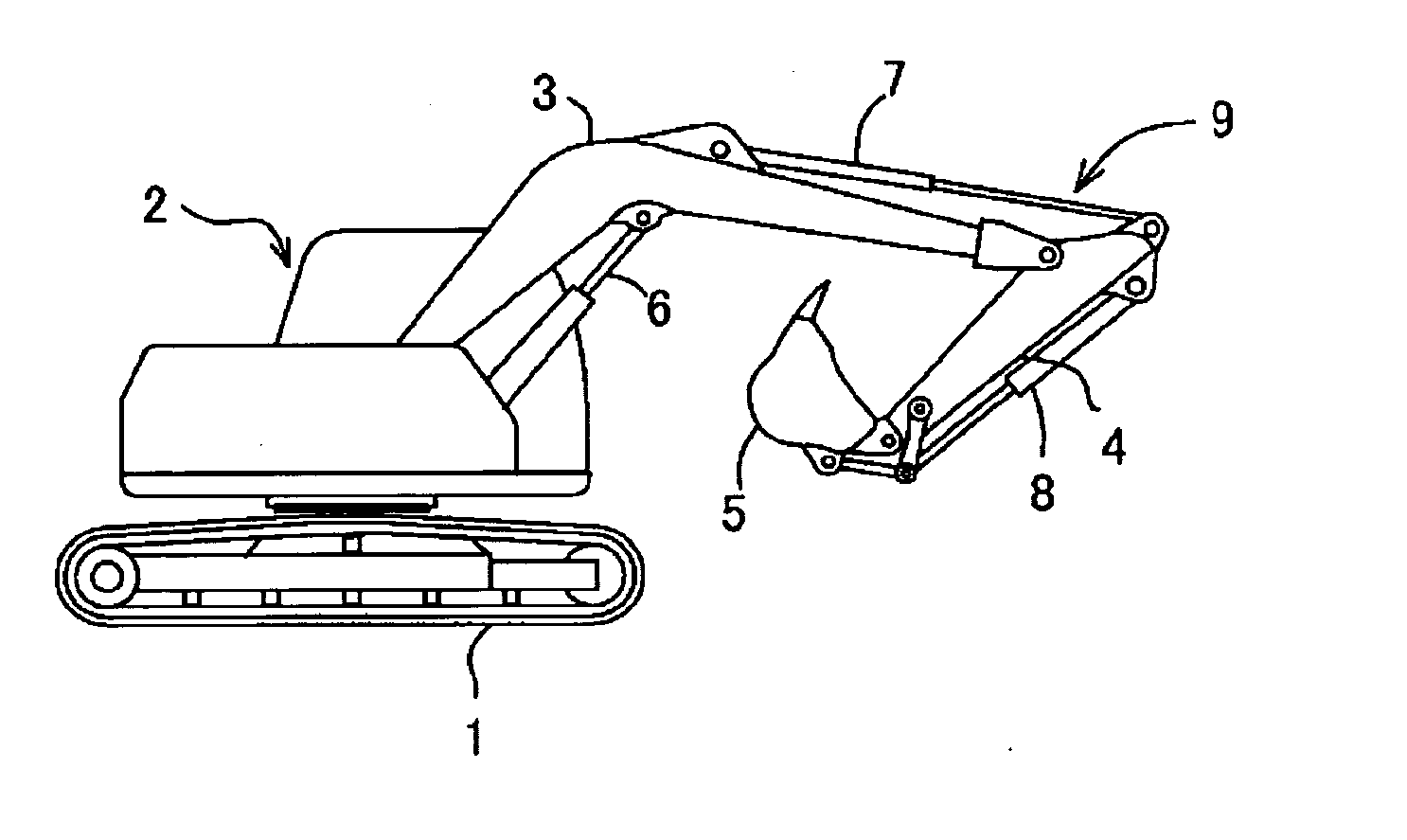
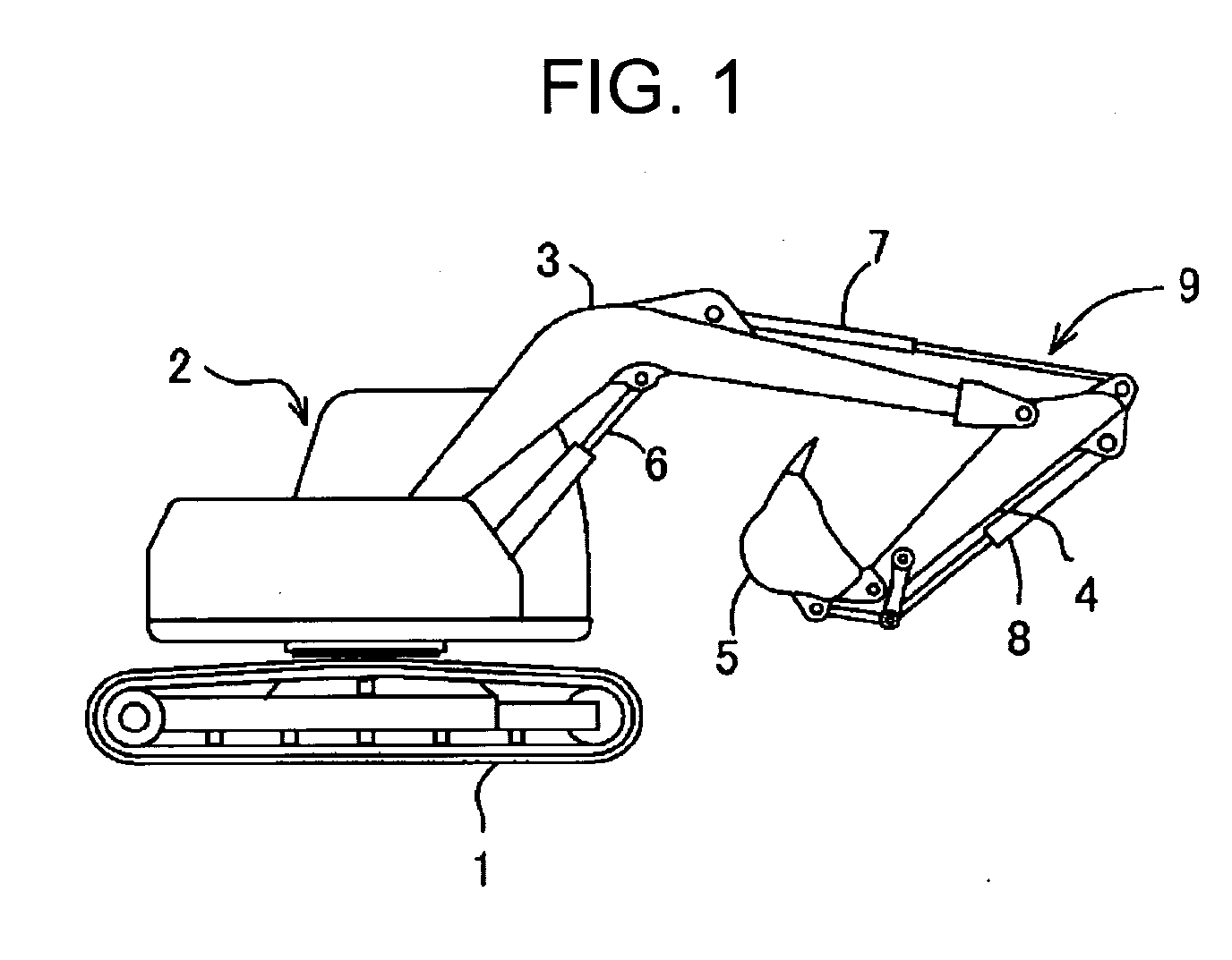
[0036]FIG. 1 illustrates a shovel to which the present invention is applied.

[0037] In the shovel, an upper rotating body 2 is rotatable around a vertical axis and mounted on a crawler type lower traveling body 1. On the upper rotating body 2, a working (excavation) device 9 which has a boom 3, an arm 4, a bucket 5, and cylinders (hydraulic cylinder) 6, 7, and 8 of each of the boom, the arm, and the bucket which drive them, is mounted.

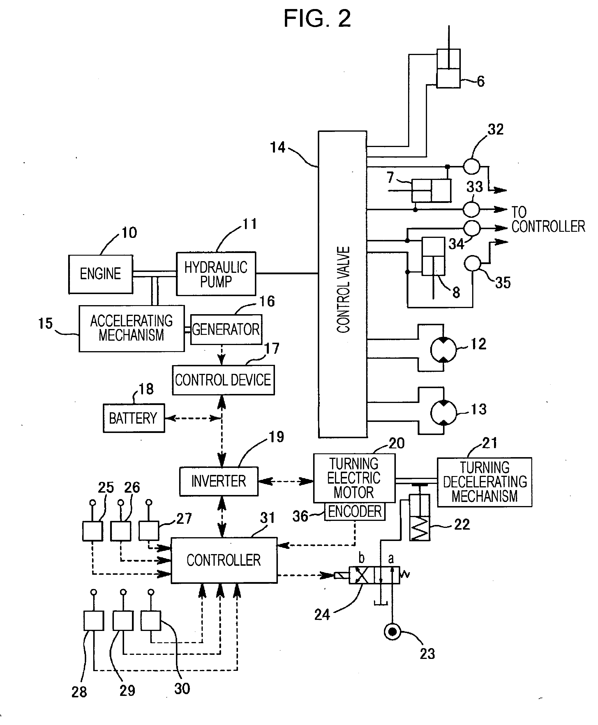
[0038]FIG. 2 illustrates a block diagram of an overall driving system and an overall control system of the shovel.

[0039] As shown in the drawing, a hydraulic pump 11 is driven by an engine 10 and the discharged oil is supplied to the cylinders 6, 7, and 8 of each of the boom, the arm, and the bucket and right and left traveling motors 12 and 13 which drive the lower traveling body 1 through a control valve 14 (although the valve is provided to each actuator, in this case, it is shown as a valve block).

[0040] Furthe...

second embodiment (see figs.4 and 5)

Second Embodiment (see FIGS. 4 and 5)

[0066] In each embodiment below, only deference from the first embodiment is described.

[0067] In the first embodiment, the main purpose is to protect the parking brake 22 and the rotating driving part when at least one of the arm operation and the bucket operation is carried out by carrying out only the release of the parking brake 22. On the other hand, in the second and other embodiments, while releasing the parking brake 22, the rotating electric motor 20 is controlled in a direction holding the upper rotating body 2 in a stopped state.

[0068] Further, in each of the second to fifth embodiments, since the configurations of the hardware themselves are similar to those in the first embodiment and only control contents differ, the configuration of the hardware shown in FIG. 2 is used and only the control contents are described.

[0069] In the second embodiment, as shown in FIG. 4, whether an arm operation exists or not is determined at step S11 a...

third embodiment (see fig.6)

Third Embodiment (see FIG. 6)

[0080] In a third embodiment, in place of the speed feedback control described in the second embodiment, a position feedback control is employed.

[0081] That is, steps S21 to 24 are similar to those in the steps S11 to S14 in FIG. 4, at step S25, a rotating position of the time is stored and at step S26, the parking brake 22 is released. Then, at step S27, the position feedback control, that is, based on a position signal from the encoder 36, by a deviation of a position at the time of control start and a position detected later, the feedback control is carried out.

[0082] In this control method, even if the rotating electric motor 20 moves due to external force if the external force is larger than electric motor torque, if the external force becomes smaller than the electric motor torque, the rotating electric motor 20 is controlled to return to a target position.

[0083] According to the position feedback control, as well as the second embodiment, when ...


PUM


Abstract

A parking brake is released by a controller and a rotating electric motor is speed-feedback-controlled or position-feedback-controlled to stop and hold an upper rotating body if at least one of arm operation, bucket operation, and travel operation is carried out in a rotating stopped state and with respect to the arm operation and the bucket operation, cylinder thrust of an arm cylinder or a bucket cylinder is greater or equal to a set value. Thereby, a parking brake and a rotating driving part can be prevented from being damaged by rotating external force generated by excavation reaction force or the like and a rotating body can be stopped and held.

Description

TECHNICAL FIELD [0001] The present invention relates to a rotating type working machine which drives and rotates a rotating body by an electric motor. BACKGROUND ART [0002] In rotating type working machines such as a shovel or a crane, as described in the patent literature 1, electric motor driving systems for controlling a rotating direction and a rotating speed by using an electric motor as a rotating driving source and by changing rotation directions and speeds of the electric motor have been known. [0003] According to the electric motor driving systems, energy efficiency can be improved as compared to hydraulic motor driving systems. [0004] Further, in the electric motor driving systems, as described in the patent literature 2, a technique in which a parking brake is operated in a state that rotating operation is stopped, and a rotating body is stopped and held has been known. [0005] In the working machines equipped with a parking brake, external force (hereinafter, referred to ...

Claims


Application Information

Patent Timeline
Patent Type & Authority Applications(United States)
IPC IPC(8): E02F5/02E02F9/22E02F9/24F15B11/08
CPCE02F9/123E02F9/24E02F9/2217E02F9/128E02F9/2095
Inventor YOSHIMATSU, HIDEAKI
Owner KOBELCO CONSTR MASCH CO LTD
Why Eureka
Try Eureka