Method for producing a ceramic filter element

Inactive Publication Date: 2007-08-16
MANN HUMMEL GMBH
View PDF3 Cites 31 Cited by
  • Summary
  • Abstract
  • Description
  • Claims
  • Application Information

AI Technical Summary

Benefits of technology

[0018] To keep the shape of the superimposed substrate sheets prior to firing, it can be advantageous to bond them together by me

Problems solved by technology

A disadvantage in this manufacturing process is that it is relatively costly.
A further disadvant

Method used


Image

  • Method for producing a ceramic filter element
  • Method for producing a ceramic filter element

Examples


Embodiment Construction

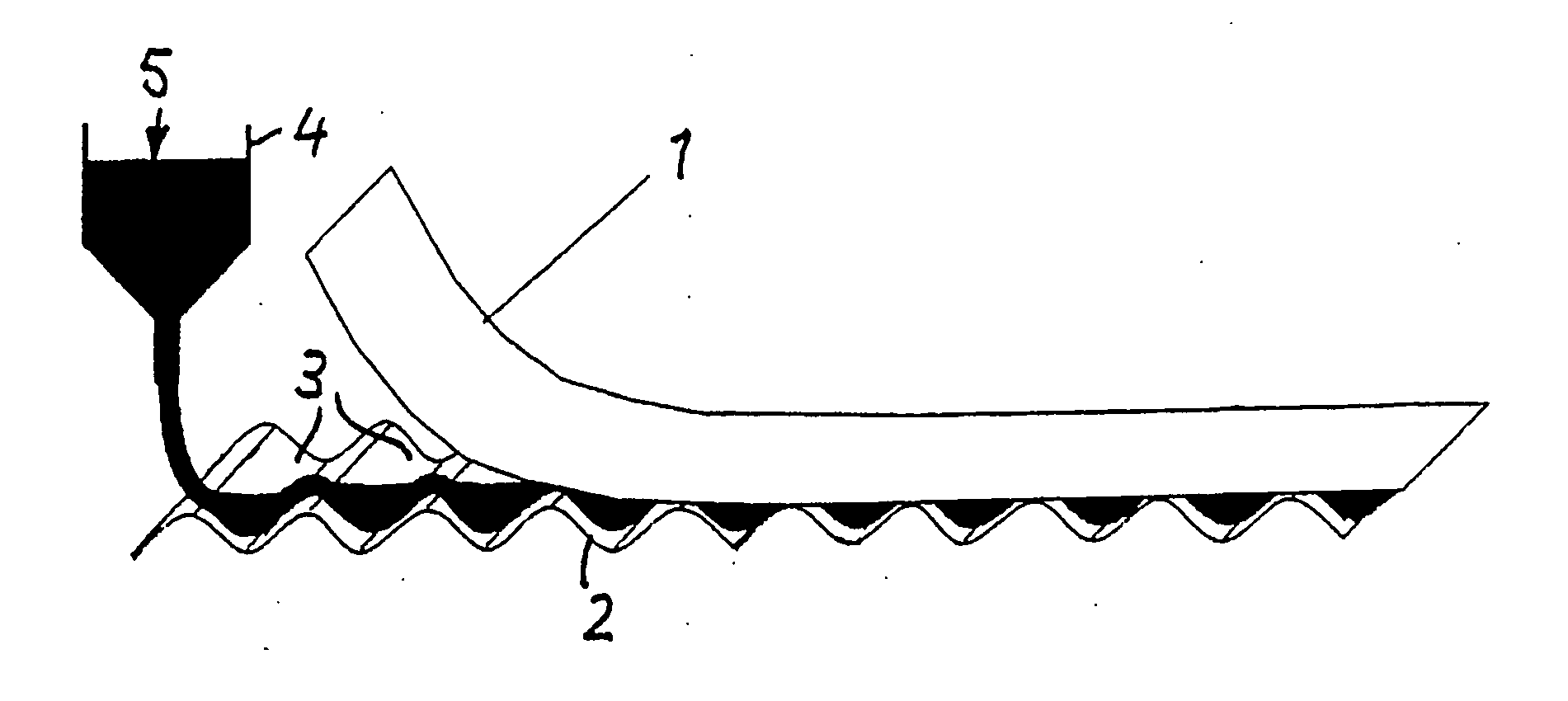
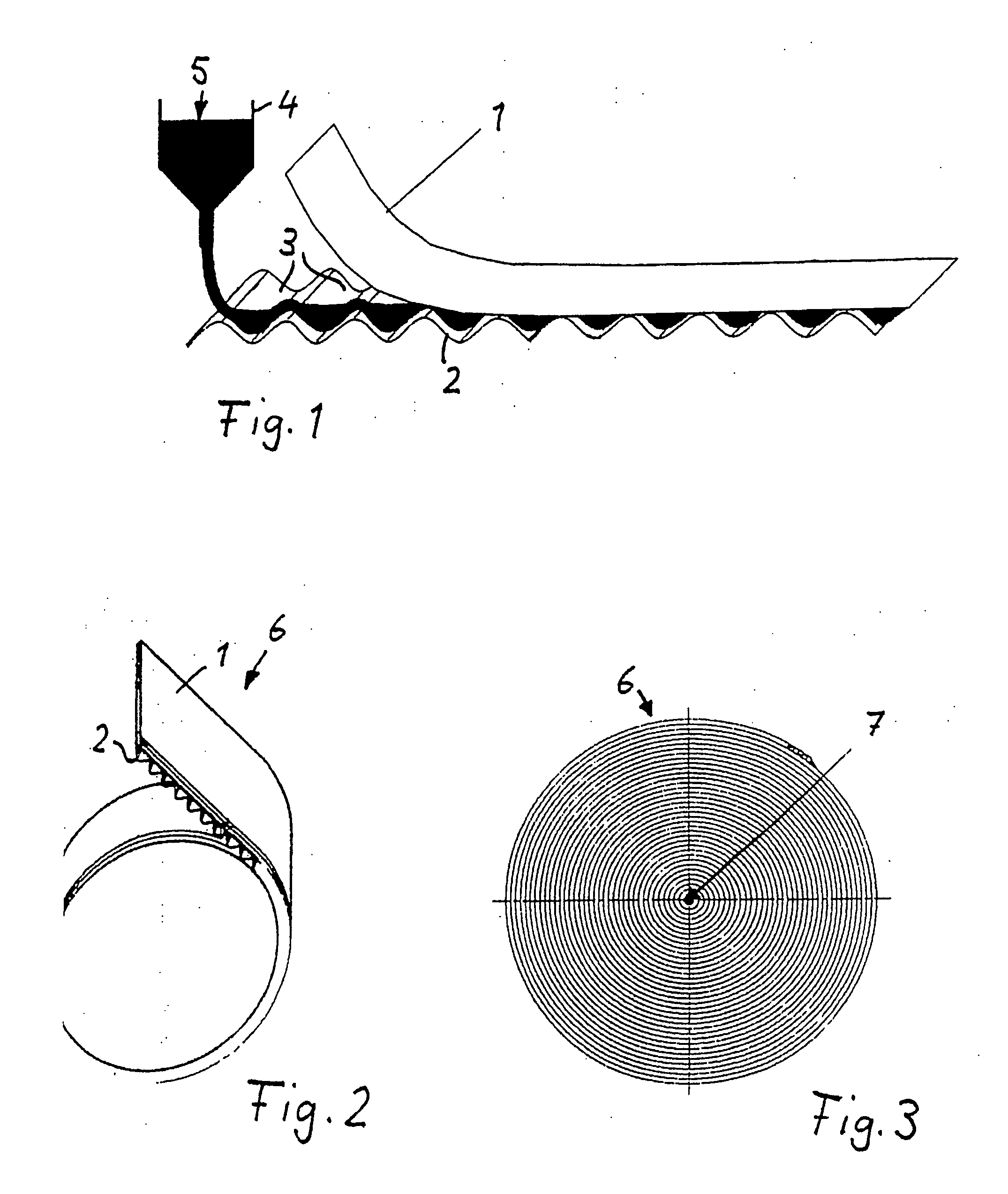
[0024] As illustrated in FIG. 1, to produce a filter element intended for use in an exhaust gas filter for internal combustion engines, two substrate sheets 1 and 2 are superimposed on each other and bonded together by means of a ceramic adhesive 5. The substrate sheets 1 and 2 are paper sheets and are made of cellulose, but other organic or inorganic combustible substances may also be considered. The lower substrate sheet 2 is corrugated to create parallel extending flow paths 3. The upper substrate sheet is smooth. The two substrate sheets are bonded together by means of an adhesive 5 delivered from a hopper 4 and introduced in the region of one end face of the flow paths 3. In addition to bonding the two substrate sheets together, the adhesive has the function of closing the flow paths 3 at one end.

[0025] The use of a ceramic adhesive has the advantage that it is preserved even after subsequent firing, so that the flow paths remain securely closed. If only the two substrate shee...


PUM

PropertyMeasurementUnit
Pore sizeaaaaaaaaaa
Electrical conductivityaaaaaaaaaa
Flow rateaaaaaaaaaa

Abstract

A method of producing a ceramic filter element suitable for use in an exhaust filter for an internal combustion engine, during which a combustible, non-ceramic support web is impregnated with a ceramic slip and formed into a desired geometric shape in either order, and then the impregnated and formed web is fired until the support web is burned out and a rigid ceramic filter body is formed.

Description

CROSS REFERENCE TO RELATED APPLICATIONS [0001] This application is a continuation of international patent application no. PCT / EP2005 / 052884, filed Jun. 21, 2005, designating the United States of America, and published in German on Jan. 19, 2006 as WO 2006 / 005668, the entire disclosure of which is incorporated herein by reference. Priority is claimed based on Federal Republic of Germany patent application no. DE 10 205 403 34 94.3, filed Jul. 10, 2004.BACKGROUND OF THE INVENTION [0002] The invention relates to a method for manufacturing a ceramic filter element which may be used, for example, as an exhaust filter for an internal combustion engine. [0003] Published Japanese patent application no. JP 63134020 A describes a ceramic filter element for an exhaust filter in an internal combustion engine that is constructed from a corrugated, spirally wound filter sheet. To manufacture the filter sheet, heat-resistant inorganic fibers in an aqueous suspension are mixed with ceramic powder a...

Claims


Application Information

Patent Timeline
IPC IPC(8): H03H9/00
CPCB01D39/2082Y10T29/49083B01D46/527B01D2279/30C04B38/0083C04B2111/00793F01N3/0222F01N2330/06B01D46/0001Y10T29/496Y10T29/49345Y10T29/49604Y10T156/1057Y02T10/20C04B35/10C04B35/185C04B35/195C04B35/565C04B38/0045C04B38/0675Y02T10/12B01D39/20
Inventor GERLACH, KARINTUDYKA, STEFAN
Owner MANN HUMMEL GMBH
Why Eureka
Try Eureka