
Binary optics SAL seeker (BOSS)

a binary optics and sal seeker technology, applied in direction controllers, instruments, weapons, etc., can solve the problems of large field of regard, disadvantageous reduction, complex and cost, etc., and achieve the effect of maintaining compatibility with fast optics, large fov and compact design

Active Publication Date: 2007-08-16
LOCKHEED MARTIN CORP
View PDF17 Cites 12 Cited by
  • Summary
  • Abstract
  • Description
  • Claims
  • Application Information

AI Technical Summary

Benefits of technology

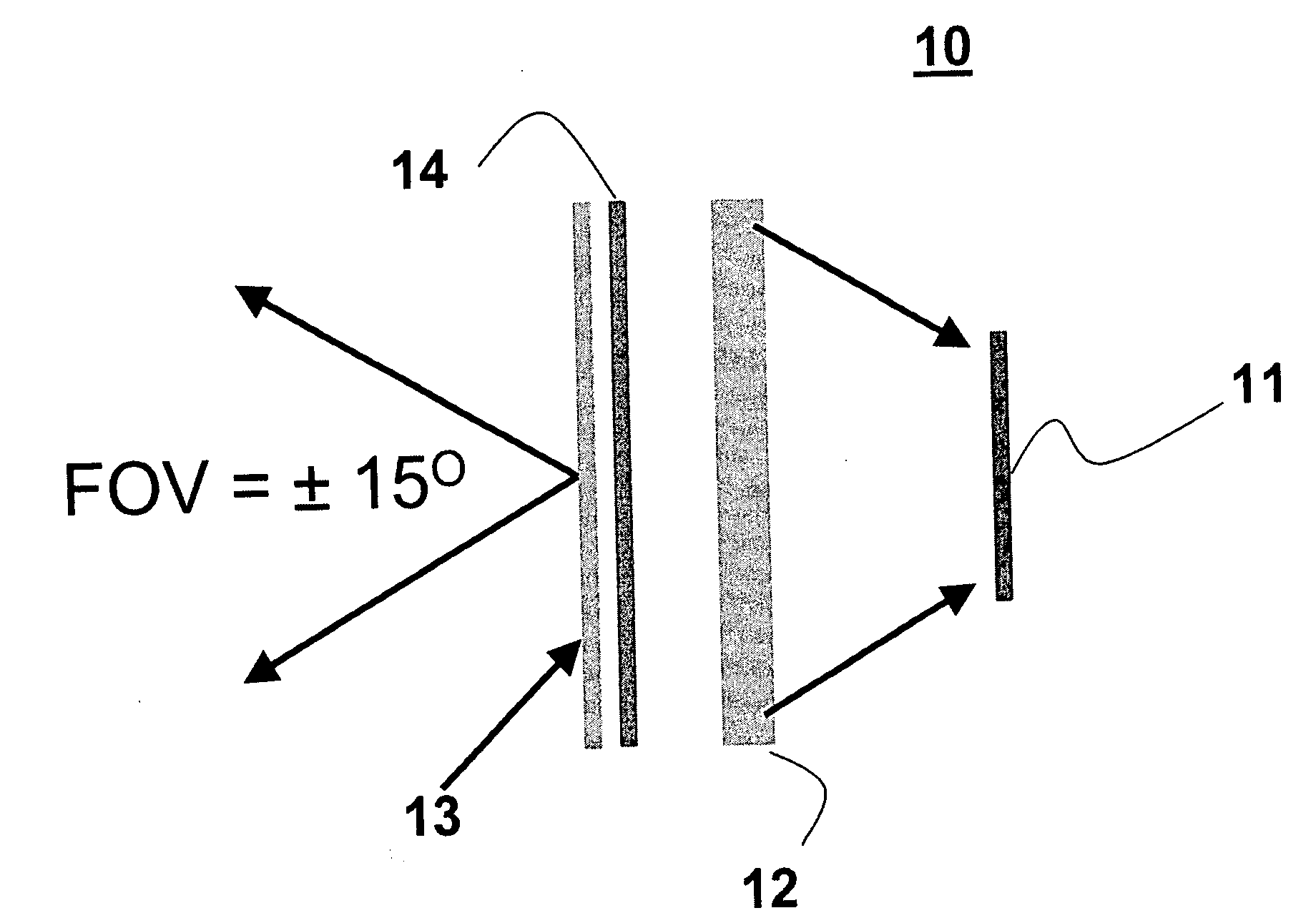
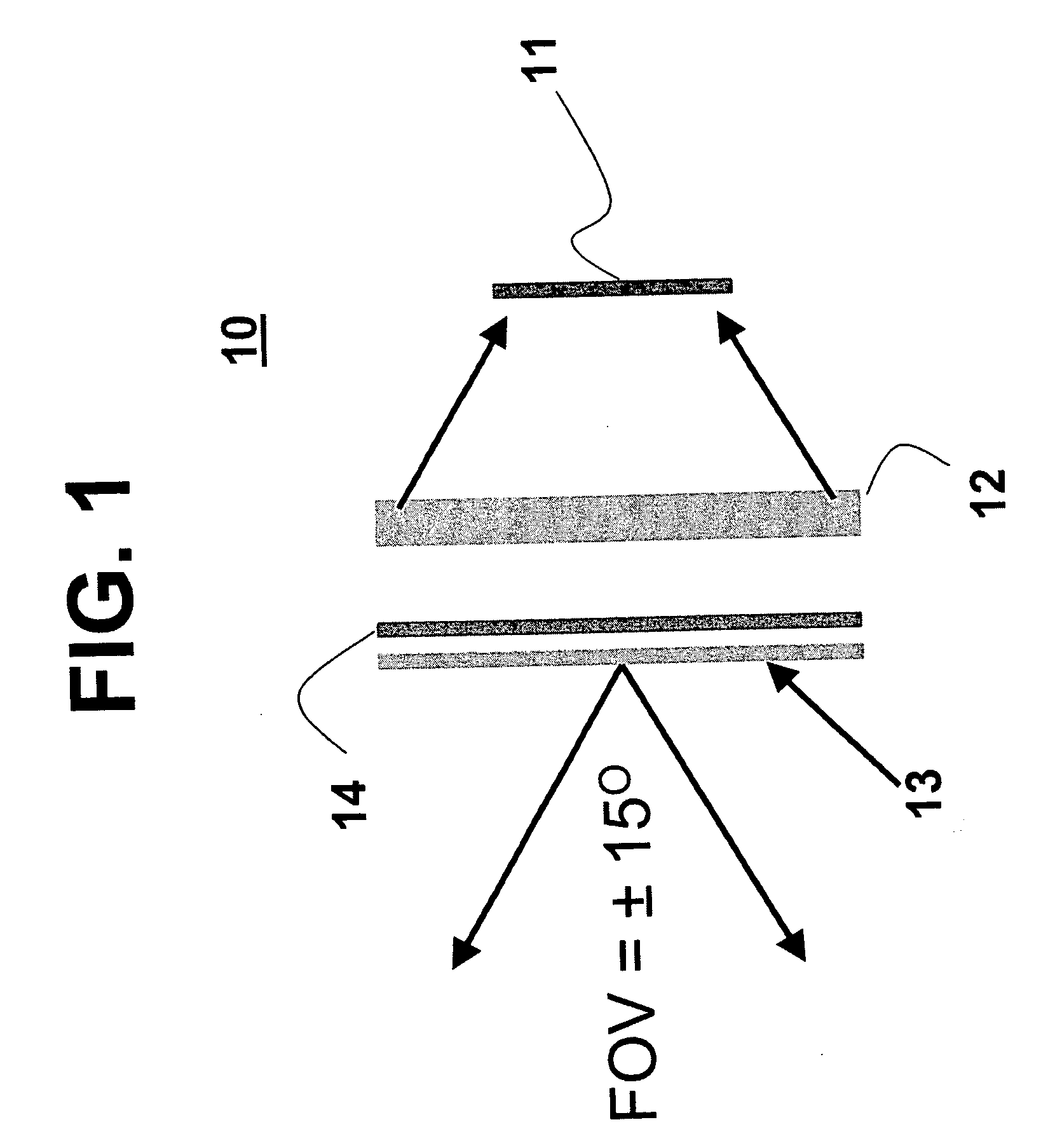
[0011] The method and system of the present invention relates to a strap down SAL seeker having novel optical components that overcomes the atmospheric scintillation and spot uniformity problems of a conventional SAL seeker. The SAL seeker of the present invention includes an engineered diffuser to solve spot uniformity and atmospheric scintillation problems while maintaining compatibility with fast optics, a large FOV and c

Problems solved by technology

The elimination of the gimbal system advantageously reduces the complexity and cost of the SAL seeker, but it also disadvantageously reduces the FOR.
SAL seekers, however, require a relatively large field of regard, relatively fast optics, anti-scintillation capability and small physical size.
The current optical designs that attempt to meet these conflicting requirements, result in a blur spot that is extremely non-uniform.
Because this type of seeker has passive gimbals, it is not considered to be a strap down seeker, but it has similar requirements and issues as a strap down seeker.
In addition, atmospheric scintillation and uniformity problems further aggravate the performance of SAL seekers.
The spot uniformity problem further compounds the situation, because the laser spot typically does not have a uniform energy distribution.
A non-uniform distribution of laser energy means that the laser spot does not appear as a well-defined spot of illumination to the detector, and the non-uniformity complicates image processing of the laser spot.
Previous solutions to the scintillation problem have been expensive (use of a fiber optic faceplate) or have produced poor spot uniformity (use of a spherical distortion lens).
Moreover, the previous solutions to reduce the scintillation have actually aggravated the uniformity problem.
For example, the use of carefully designed aberrations in the optics to reduce scintillation produce significant spot non-uniformity and a non-linear response in a strap down seeker.

Method used


Image

  • Binary optics SAL seeker (BOSS)
  • Binary optics SAL seeker (BOSS)
  • Binary optics SAL seeker (BOSS)

Examples


Embodiment Construction

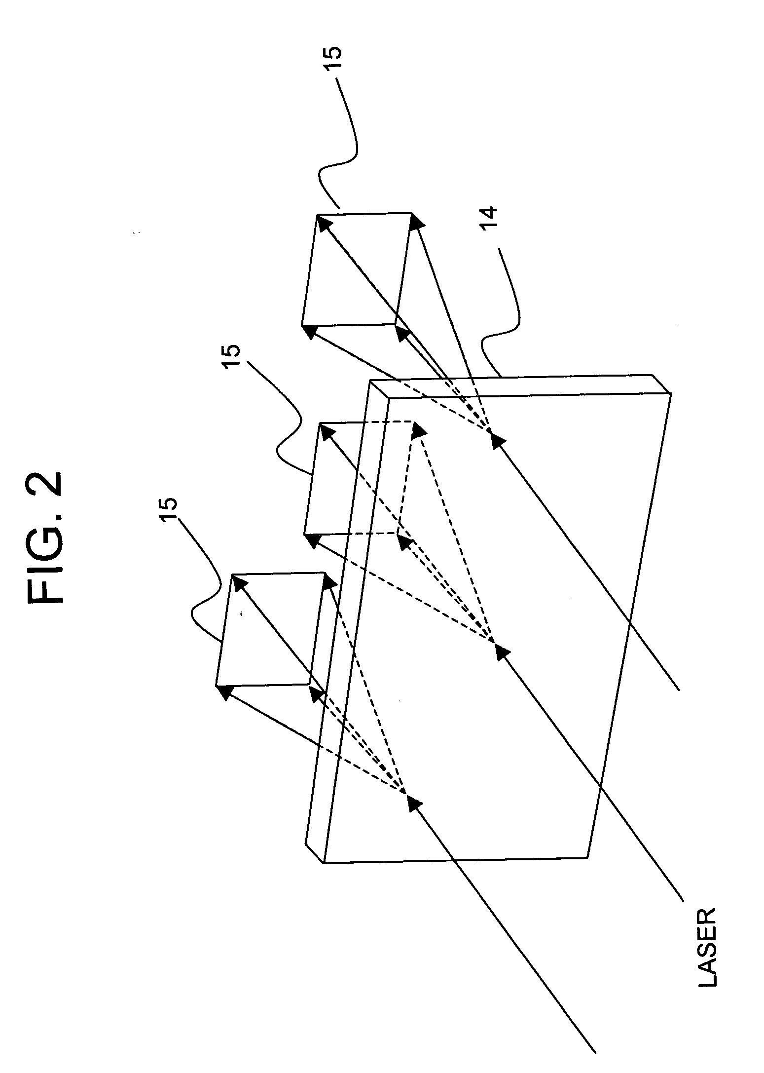
[0016] The present invention relates to a SAL seeker having an engineered diffuser disposed at its aperture. Engineered diffusers are a new class of optical elements that are designed and generated by a computer. The computer is used to calculate the shapes of various microlenses which are formed in a substrate using a laser. A radius of curvature, conic constant, and aspheric coefficients define each microlens element of the engineered diffuser. At the normal SAL wavelength of 1.06 um, the engineered diffuser is computer generated, and it is formed on an inexpensive plastic disk that can be replicated in production quantities at a relatively low cost. The engineered diffuser of the present invention is preferably disposed at the entrance aperture of the SAL seeker, and the engineered diffuser distributes the incoming laser energy in a predetermined distribution or shape that is projected onto the detector.

[0017] Referring now to FIG. 1, a schematic diagram of the SAL seeker 10 of ...


PUM


Abstract

The present invention relates to a strap down SAL seeker that includes an optical system having an engineered diffuser for transforming a laser spot into a uniform distribution of optical energy with a predetermined shape. The predetermined shape is preferably a square “top hat” or uniform scatter pattern. The SAL seeker further includes a silicon quad detector, having a focal plane defined by at least two axes. The detector is operatively associated with the engineered diffuser, and it generates signals indicative of the position of the optical energy with respect to the focal plane of the detector.

Description

BACKGROUND OF THE INVENTION [0001] 1. Field of the Invention [0002] The present invention relates generally to a SAL seeker, and more specifically to an engineered diffuser utilized in conjunction with a strap down SAL seeker or a velocity pursuit SAL seeker. [0003] 2. Description of the Related Art [0004] Semi-active laser (“SAL”) seekers are well known in the art, and a representative example is described in U.S. Pat. No. 6,262,800, entitled “Dual Mode Semi-Active Laser / Laser Radar Seeker”, by Lewis Minor, and assigned to Lockheed Martin Corporation, the assignee of the present application. The '800 patent describes a marking and guidance system for use on military aircraft to support ground operations. With a SAL seeker system, a narrow laser beam is produced and transmitted toward a target from a laser designator aircraft or from a forward observer located on the ground. The operator of the laser designator directs the laser illumination towards a selected target, thereby design...

Claims


Application Information

Patent Timeline
IPC IPC(8): F41G7/00
CPCF41G7/226F42B15/01F41G7/2293
Inventor LAYTON, ALLEN C.
Owner LOCKHEED MARTIN CORP
Learn More