Manufacturing method of bearing member and manufacturing method of sleeve unit
a manufacturing method and bearing technology, applied in the direction of bearing unit rigid support, manufacturing tools, instruments, etc., can solve the problems of contaminating lubricating oil, affecting the characteristics of the motor, and difficult to maintain a predetermined thickness for the flange portion in continuous manner, so as to achieve superior reliability and durability, and achieve precise dimension formation effective
- Summary
- Abstract
- Description
- Claims
- Application Information
AI Technical Summary
Benefits of technology
Problems solved by technology
Method used
Image
Examples
first preferred embodiment
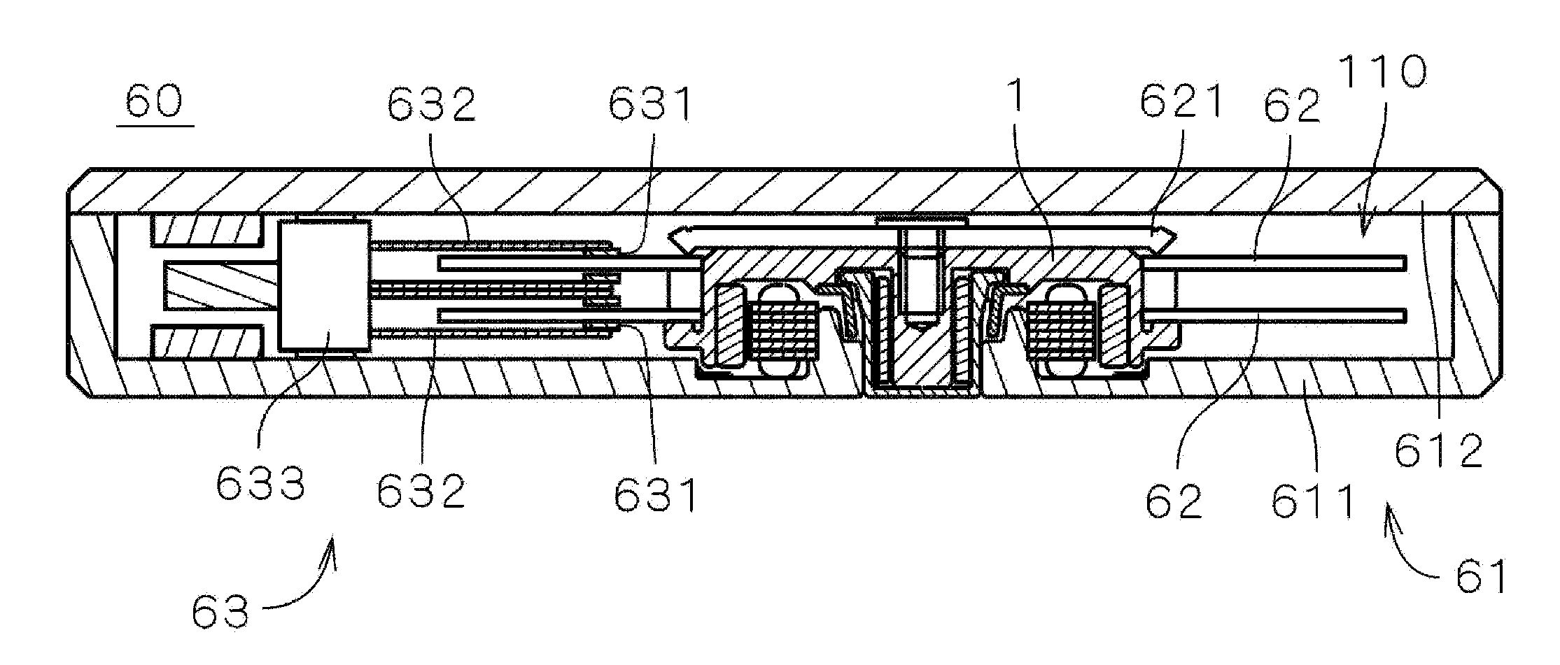
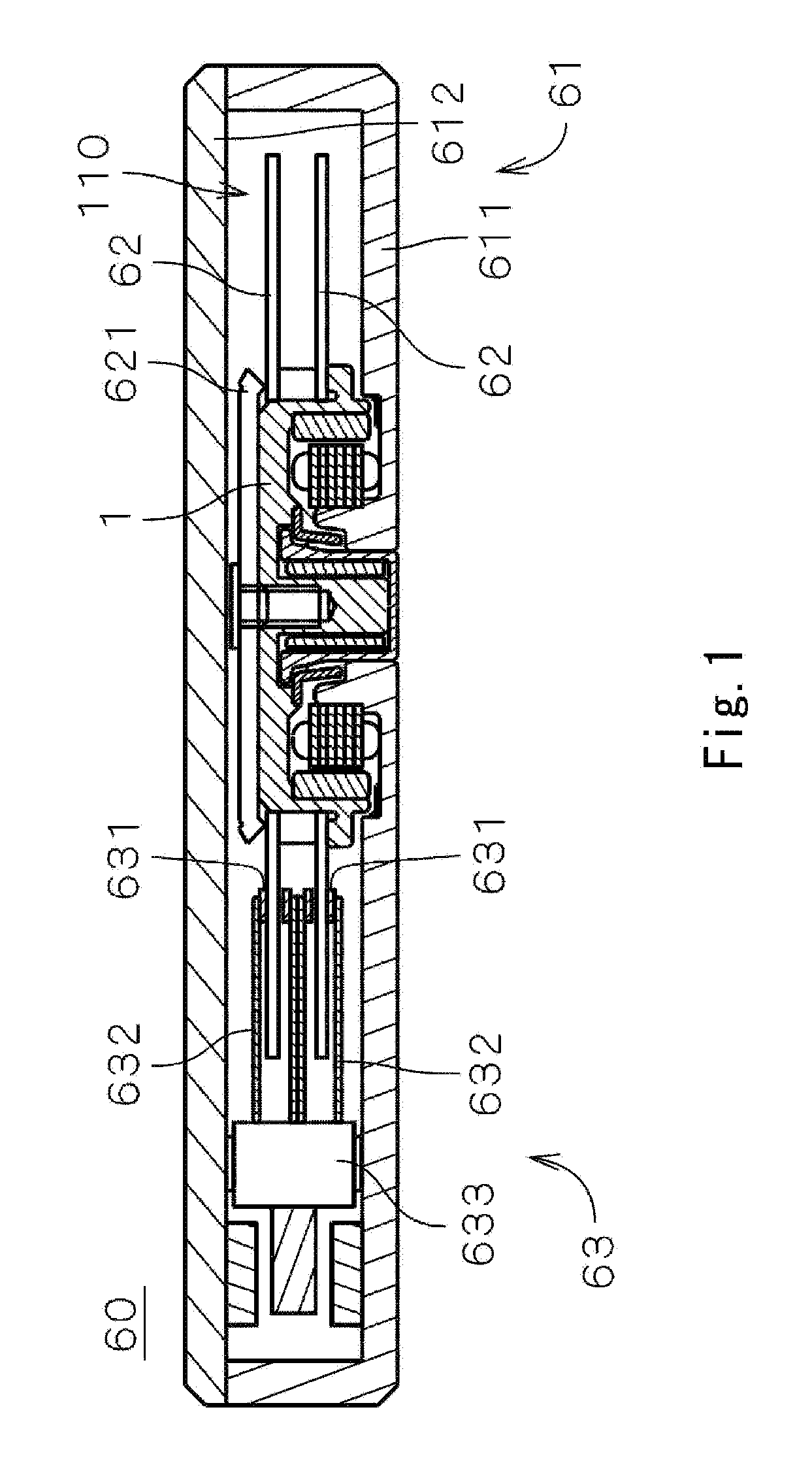
[0029]FIG. 1 is a diagram showing an internal configuration of a recording disk drive device 60 including therein an electrical spindle motor 1 (hereinafter, referred to as “motor 1”) according to a first preferred embodiment of the present invention.
[0030] The recording disk drive device 60 is a hard disk drive device which preferably includes two discoid shaped recording disks 62 used for recording data, an access section 63 used for storing data in the recording disk 62 and / or reading data in the recording disk 62, an electrical motor 1 for retaining and rotating the recording disk 62, and a housing 61 for accommodating in an inner space 110 therein the recording disk 62, the access section 63 and motor 1.
[0031] As shown in FIG. 1, the housing 61 includes a substantially cup-shaped first housing member 611 and a plate shaped second housing member 612. The first housing member 611 includes at a top portion thereof an opening. The first housing member 611 contains and holds the m...
second preferred embodiment
[0074] Hereinafter, a second preferred embodiment of the motor 1 (hereinafter referred to as a motor 1a) of the present invention will be described. FIG. 6 is a cross sectional diagram showing an enlarged view of a portion of the motor 1a according to the second preferred embodiment of the present invention. The motor 1a preferably includes a sleeve unit 222a having a shape that is different from the sleeve housing 222 as shown in FIGS. 2 and 3.
[0075] In the rotor hub 31, instead of the annular shaped member 313, a substantially cylindrically shaped cylinder portion 3132a and an annular portion 3131a are preferably provided. The cylinder portion 3132 at a portion thereof surrounding the sleeve housing 222a protrudes in the downward direction. The annular portion 3131a at a bottom end of the cylinder portion 3132a protrudes toward the central axis J1. Other than the aforementioned differences, the rotor hub 31 according to the present preferred embodiment preferably has an identical...
third preferred embodiment
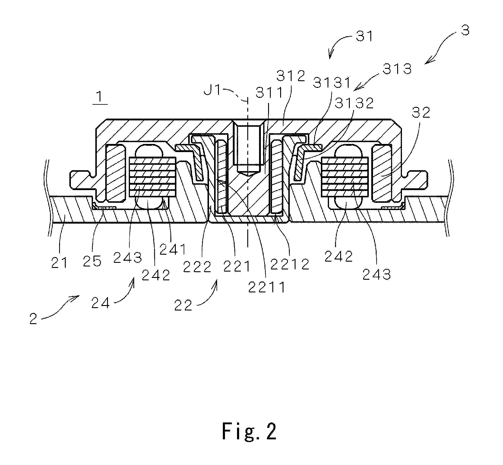
[0079] Hereinafter, a third preferred embodiment of the motor 1 (hereinafter referred to as a motor 1b) of the present invention will be described. FIG. 7 is a cross sectional diagram showing an enlarged view of a portion of the motor 1b according to the third preferred embodiment. The motor 1b includes, instead of the sleeve unit 22 as shown in FIGS. 2 and 3, a substantially cylindrically shaped sleeve 22a which defines a bearing member and is a seamless component made of a metal material, and a substantially discoid shaped bottom portion member 23 which closes an opening at a bottom of the sleeve 22a. In FIG. 7, elements similar to those shown in FIGS. 2 and 3 are denoted by similar reference numerals.
[0080]FIG. 8 is a flowchart showing a flow of steps required to manufacture the sleeve 22a. Note that steps following a step S22 shown in FIG. 8 are identical to steps S13 through S17 shown in FIG. 4. First, a preliminary shape of the sleeve 22a is forged out of a metallic work piec...
PUM
| Property | Measurement | Unit |
|---|---|---|
| depth | aaaaa | aaaaa |
| depth | aaaaa | aaaaa |
| distance | aaaaa | aaaaa |
Abstract
Description
Claims
Application Information
 - R&D
- Intellectual Property
- Life Sciences
- Materials
- Tech Scout
- Unparalleled Data Quality
- Higher Quality Content
- 60% Fewer Hallucinations
Browse by: Latest US Patents, China's latest patents, Technical Efficacy Thesaurus, Application Domain, Technology Topic, Popular Technical Reports.
© 2025 PatSnap. All rights reserved.Legal|Privacy policy|Modern Slavery Act Transparency Statement|Sitemap|About US| Contact US: help@patsnap.com


