Radiotomography apparatus

a technology of radiotomography and apparatus, applied in the field of radiotomography apparatus, can solve the problems of decreasing the utilization rate of those segments, increasing reducing the time resolution, so as to reduce the ineffective radiation exposure of objects, enhance spatial resolution or temporal resolution, and improve the effect of temporal resolution

Active Publication Date: 2007-08-16
FUJIFILM HEALTHCARE CORP
View PDF16 Cites 81 Cited by
  • Summary
  • Abstract
  • Description
  • Claims
  • Application Information

AI Technical Summary

Benefits of technology

[0024] It is therefore possible to provide a radiotomography apparatus that can contribute to enhancing a spatial resolution or a temporal resolution when collecting divided image data of the same phas

Problems solved by technology

As a result, the temporal resolution declines.
In contrast, when the table feeding speed is slowed down to increase redundancy, since the number of segments used for reconstruction is fixed as the minimum number of da

Method used


Image

  • Radiotomography apparatus
  • Radiotomography apparatus
  • Radiotomography apparatus

Examples


first embodiment

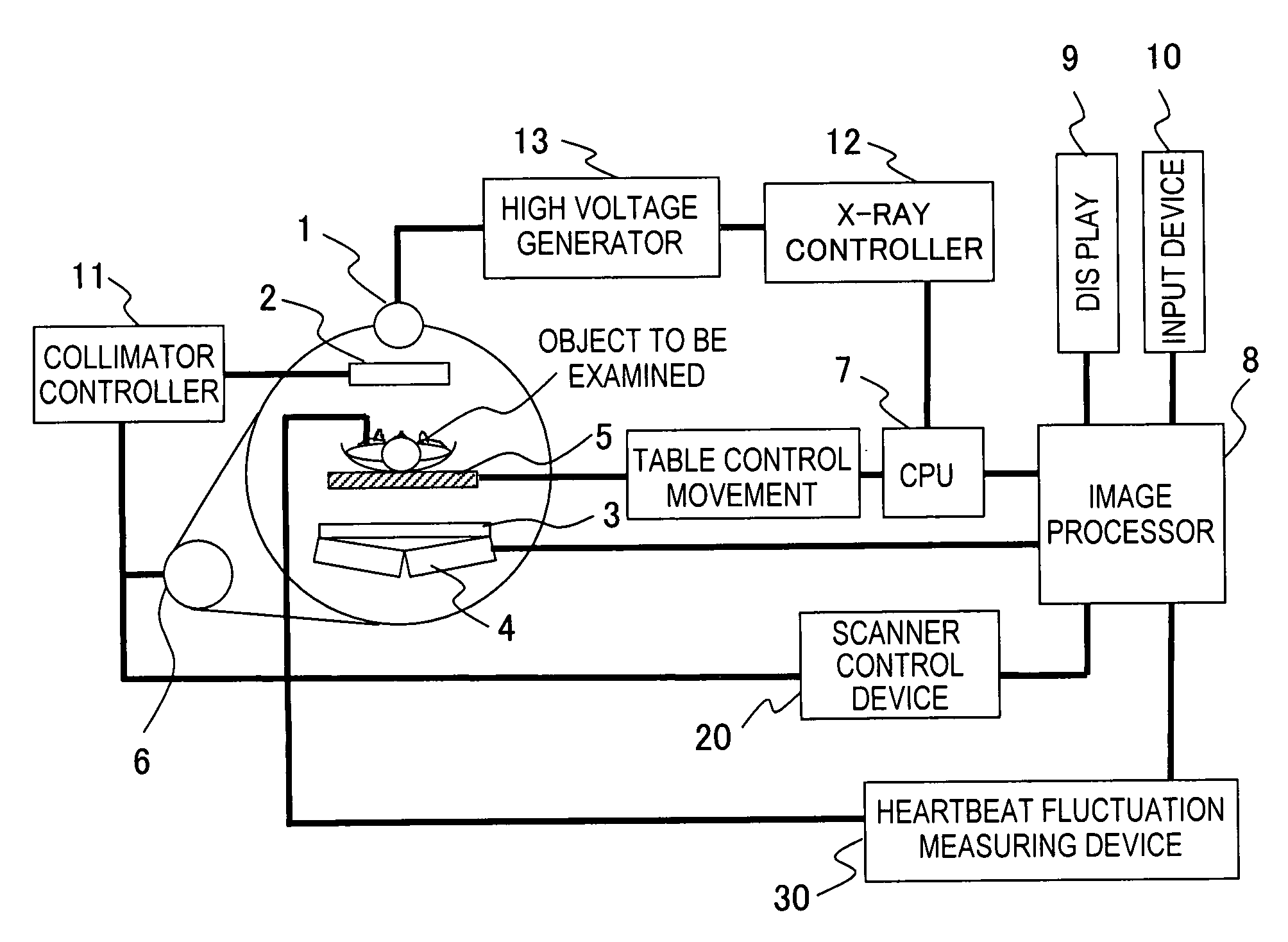
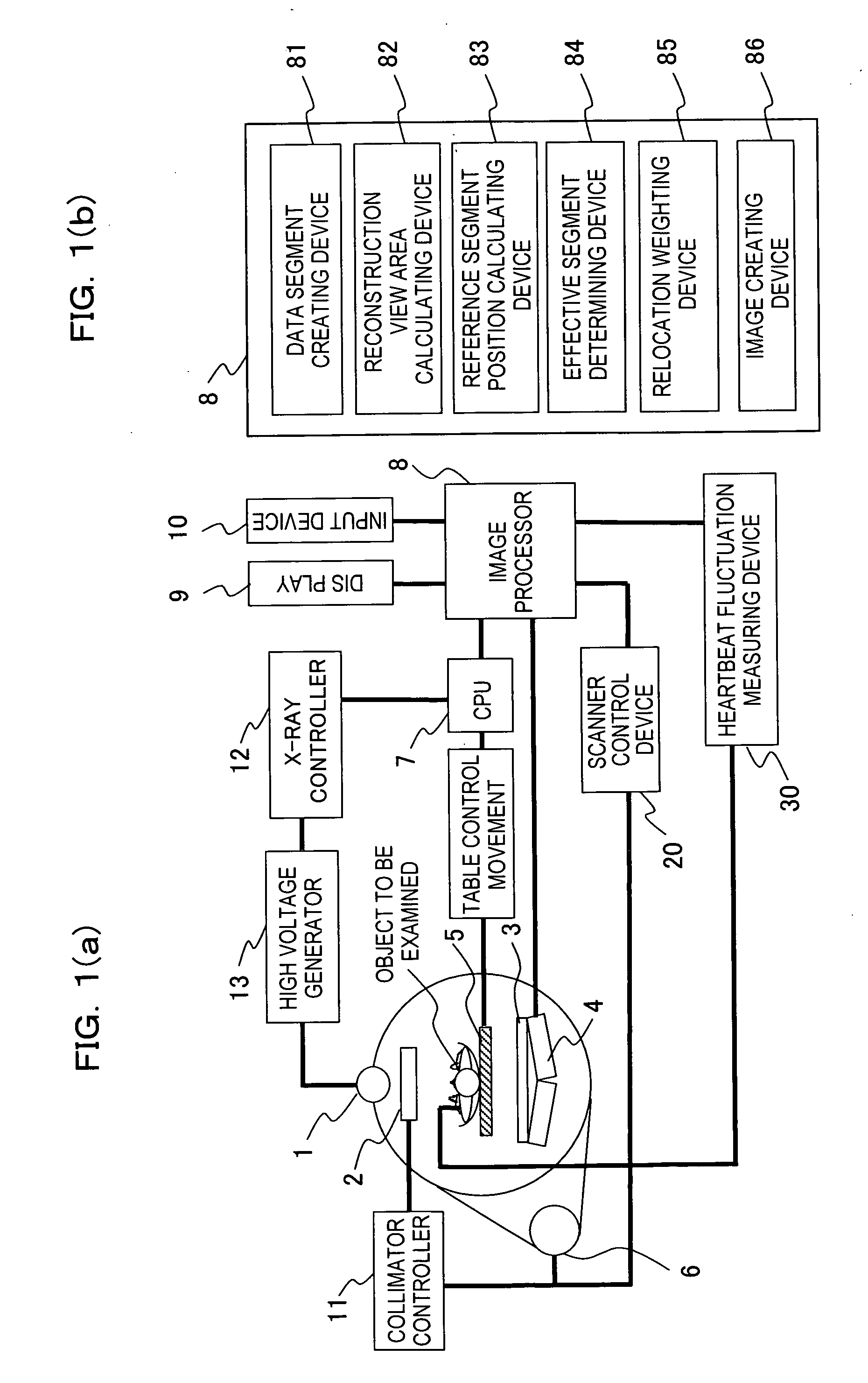
[0082]FIG. 1 is an overall configuration view that illustrates a multislice X-ray CT apparatus using a cone beam X-ray that is one example of an X-ray CT apparatus according to this invention. The X-ray CT apparatus shown in FIG. 1 employs the so-called rotate-rotate (third generation) scanning method.

[0083] The X-ray CT apparatus shown in FIG. 1 comprises an X-ray tube 1, a collimator 2, an X-ray detector 3 as X-ray detecting device, a preamplifier 4, a table 5, a rotational driving apparatus 6 that implements a predetermined scanning speed, a central control unit (CPU) 7, an image processor 8, a display 9, an input device 10, a collimator controller 11, an X-ray controller 12, a high voltage generator 13, a scanner control device 20 and a heartbeat fluctuation measuring device 30. However, the heartbeat fluctuation measuring device 30 need not necessarily be included in the configuration of the X-ray CT apparatus according to this invention, and it is sufficient that it can be co...

second embodiment

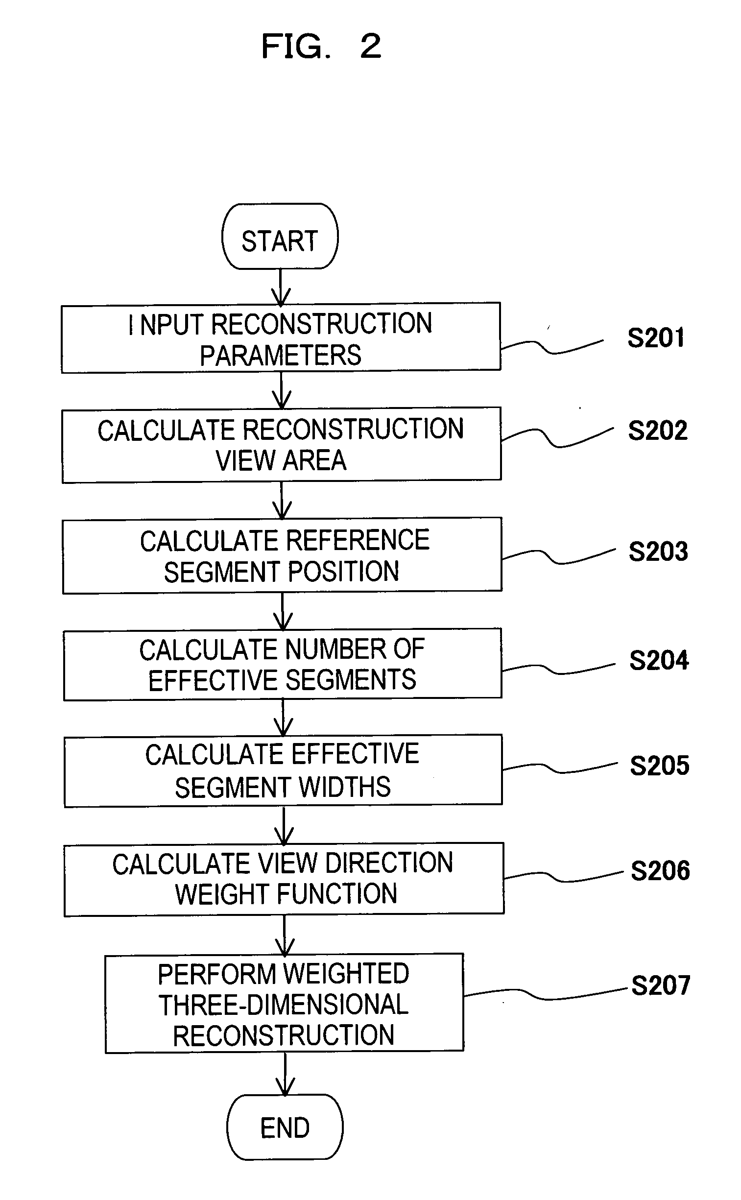
[0155] The second embodiment follows substantially the same procedures from step S201 to step S204 in FIG. 2 as described in the first embodiment. Consequently, unless specifically stated otherwise, the reference symbols used for this embodiment are the same as those used in Embodiment 1. While according to the first embodiment the relocation relating to FIG. 6 was related to full reconstruction performed in a 2π (360°) area, in Embodiment 2 half reconstruction is performed in a π (180°) area. Hereunder, Embodiment 2 is described with reference to FIG. 2 and FIG. 13.

[0156] In step S205 in FIG. 2, a segment width is calculated. First, it is assumed that up to step S204, X-ray transmission data as shown in FIG. 13(a) was obtained. Reference segment positions 65 to 69 shown in FIG. 13(a) are, for example, segment data that correspond to the reference segment positions 61 to 65 that were recognized as effective segment positions in FIG. 5. In this case, L0 and L1 are the starting edge ...

third embodiment

[0163] Although the processing of step S202 in the third embodiment is different to that of the first embodiment, the other steps are the same as those of the first embodiment and therefore a description of those steps is omitted. Hereunder, the difference with the first embodiment is described. Unless specifically stated otherwise, the reference numerals used correspond to the parts that are the same as in the first embodiment.

[0164] Although in the prior art the segments to be used for reconstruction are uniformly determined for the entire tomogram, and in the first embodiment the reconstruction view area 70 was calculated according to the FOV, according to the present embodiment the reconstruction view area 70 is calculated for each pixel.

[0165] In FIGS. 3(a) and (b), when a reconstruction pixel position is taken as I (xi,yi,zi), the position of an X-ray source is taken as S (xs,ys,zs), and row denotes the number of rows of the detector, the width R [rad] of a reconstruction vi...


PUM


Abstract

A radiotomography apparatus according to the present invention includes a radiation detection device that irradiates radiation from a radiation source in multiple directions around an object to be examined and detects radiation transmitted through the object from the multiple directions; a table on which the object lies and which can move the object in a body axis direction of the object; reconstruction parameter setting device that sets reconstruction parameters that include an amount of movement of the table in the body axis direction, and that are used to reconstruct an image of the object; a reconstruction view area calculating device that calculates a reconstruction view area for at least one data segment that is necessary for a reconstruction calculation that is determined for each spatial position that is reconstructed based on the set reconstruction parameters; a reference segment position setting device that sets a reference segment position in the calculated reconstruction view area according to a phase signal that is obtained by dynamic analysis of the object; an effective segment calculating device that calculates a data segment including the set reference segment position as an effective segment using a predetermined weight function; and an image creating device that creates an image by reconstructing the calculated effective segments. It is thus possible to provide a radiotomography apparatus that can both enhance temporal resolution and reduce ineffective radiation exposure.

Description

TECHNICAL FIELD [0001] The present invention relates to a radiotomography apparatus, and more particularly to a radiotomography apparatus for the purpose of scanning sites that carry out a periodic motion in an object to be examined, such as a cardiovascular region or respiratory organ. [0002] The present application claims priority under the Paris Convention to Japanese Patent Application No. 2004-177903, Japanese Patent Application No. 2004-206814, Japanese Patent Application No. 2004-304357, and Japanese Patent Application No. 2004-359873 that are based on the Patent Law of Japan, the contents of which are incorporated herein by reference in their entirety to receive the benefit of these applications. BACKGROUND ART [0003] An X-ray CT apparatus is one kind of radiotomography apparatus. An X-ray CT apparatus irradiates X rays while rotating a rotating part equipped with an X-ray tube and an X-ray detector around the circumference of an object to be examined, and detects X rays tha...

Claims


Application Information

Patent Timeline
IPC IPC(8): H05G1/60A61B6/00G01N23/00G21K1/12A61B6/03G06T11/00
CPCA61B6/032A61B6/4085A61B6/503A61B6/027G06T11/005G06T2211/412A61B6/541
Inventor GOTO, TAIGAMIYAZAKI, OSAMUHIROKAWA, KOICHIKOKUBUN, HIROTO
Owner FUJIFILM HEALTHCARE CORP
Why Eureka
Try Eureka