Optical network element for compensating dispersion-related propagation effects

a network element and propagation effect technology, applied in the direction of distortion/dispersion elimination, fibre transmission, electrical equipment, etc., can solve the problems of channel cross talk, severe impact of cross-channel non-linear effects on wdm optical signal transmission at data rate of 10 gbit's, and approach is not compatible with state of the art 40 gbit/s systems. , to achieve the effect of minimising the impact of cross-linear effects

Inactive Publication Date: 2007-08-16
ALCATEL LUCENT SAS
View PDF3 Cites 16 Cited by
  • Summary
  • Abstract
  • Description
  • Claims
  • Application Information

AI Technical Summary

Benefits of technology

[0004]It is the object of the present invention to provide a method of compensating dispersion related propagation effects of optical WDM signals, an optical WDM transmission system as well as a network element for use in such a transmission system which overcome the above-mentioned disadvantages, thus minimising the impact of cross non-linear effects due to the interaction between adjacent channels for transmitted optical signals with a first data rate, e.g. 10 Gbit / s, while being compatible with the transmission of optical signals with a different data rate, e.g. 40 Gbit / s.
[0014]Thus, in accordance with a basic idea of the present invention, specific dispersion compensating modules (DCMs), such as GT-DCMs, are used only in network elements, such as (Reconfigurable) Optical Add / Drop Multiplexers ((R)OADMs), in which the WDM signal is demultiplexed such that only certain channels with a first data rate, e.g. 10 Gbit / s, are fed to the specific dispersion compensating module, while channels with a second data rate, e.g. 40 Gbit / s, are routed to bypass said dispersion compensating module, thus obviating said negative effects of detrimental filtering of transmitted channels.
[0016]Alternatively, in other embodiments of the network element accordance with the present invention the first dispersion compensating module may be devised in the form of one of a Virtually Imaged Phased Array (VIPA), a ring resonator, and a fibre Bragg grating (FBG) or in the form of any other Dispersion Compensation Module adapated to compensate chromatic dispersion within separate (periodic) spectral bands without canceling a group delay introduced by fibre dispersion.
[0023]Gires-Tournois dispersion compensating modules, as well as the other types of dispersion compensation modules proposed in embodiments in accordance with the present invention, do not necessarily have to be used instead of DCFs after each fibre span in an optical WDM transmission system: Preferably, for instance for reason of cost-effectiveness when modifying an existing transmission system, the number of modules such as GT-DCMs can be reduced with respect to the number of DCFs if a doubly periodic repartition map is used, which corresponds to conventional transmission systems including (R)OADMs or—more generally—transparent nodes. Accordingly, a GT-DCM or equivalent module could be inserted within the (R)OADMs only and would still significantly improve the overall system performance with respect to dispersion compensation. In accordance with the present invention, for 10 / 40 Gbit / s systems, passing of the second data rate (40 Gbit / s) channels into the GT-DCM can be avoided.

Problems solved by technology

WDM optical signal transmission at a data rate of 10 Gbit's is severely impacted by cross-channel non-linear effects when transmission occurs on low dispersion optical fibre, e.g., having a chromatic dispersion around 4 ps / nm / km or below, which is the case with almost 50% of deployed optical fibre around the world.
An optical fibre communications, cross-phase modulation in fibres can lead to problems with channel cross talk.
However, since in a GT-DCM chromatic dispersion effects are compensated per 50 GHz bands, which corresponds to the channel spacing in most of 10 Gbit / s systems, this approach is not compatible with state of the art 40 Gbit / s systems, which generally use a 100 GHz spacing due to the higher data rate.
In such systems, the use of GT-DCMs would result in strong detrimental filtering of the transmitted channels, which must be regarded as a major drawback.

Method used


Image

  • Optical network element for compensating dispersion-related propagation effects
  • Optical network element for compensating dispersion-related propagation effects
  • Optical network element for compensating dispersion-related propagation effects

Examples


first embodiment

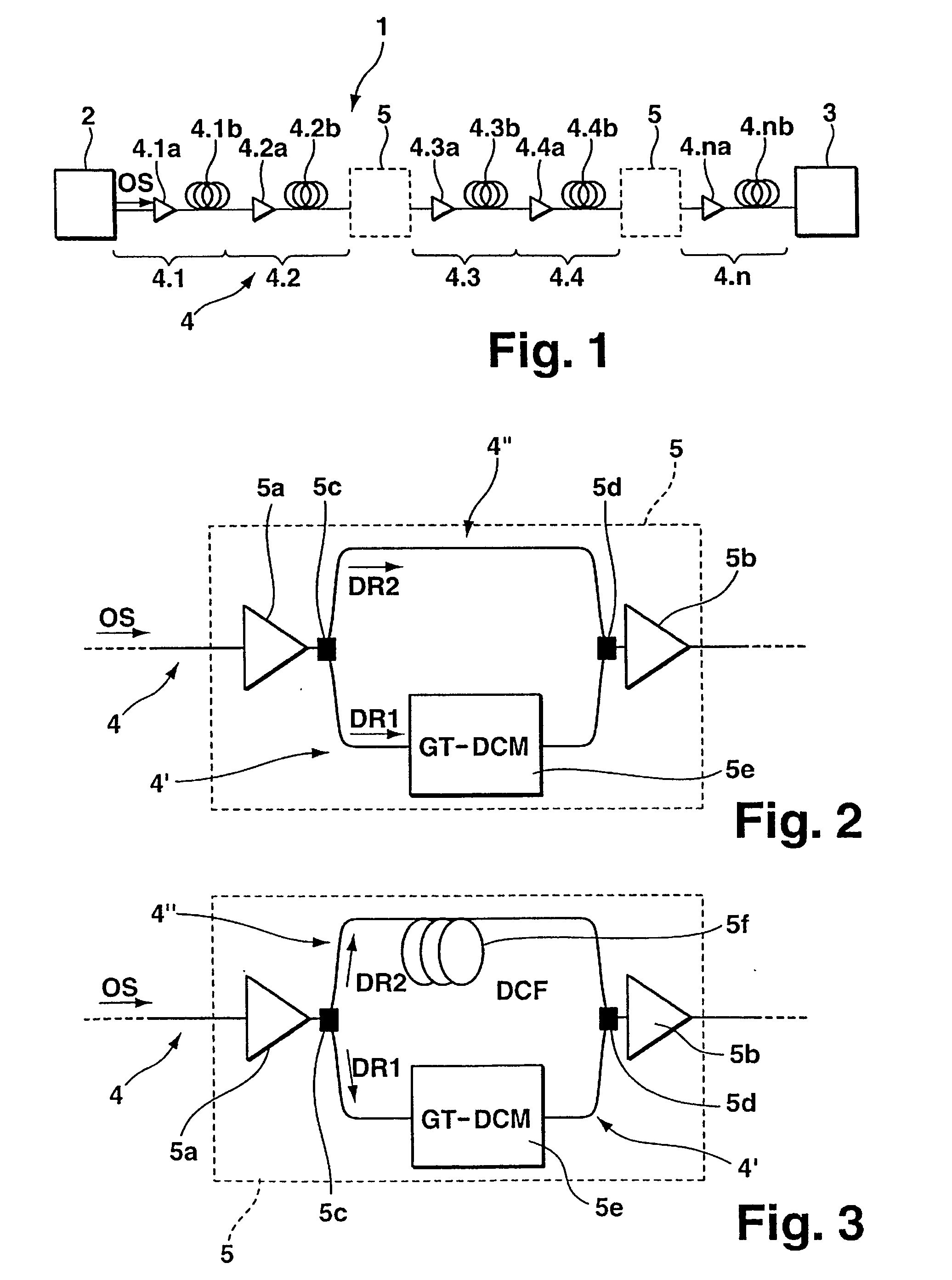
[0035]FIG. 2 shows a schematic block diagram of the network element 5 as comprised in the inventive optical transmission system 1 of FIG. 1. The network element 5 generally comprises an input amplifying means 5a and an output amplifying means 5b, e.g. input and output OFAs, respectively. Downstream of the input amplifying means 5a the network element 5 comprises a (tuneable) band demultiplexing means 5c arranged in the optical transmission link 4. At the band demultiplexing means 5c the optical transmission link 4 branches into a first branch 4′ and a second branch 4″ which recombine at a band multiplexing means 5d arranged in front of the output OFA 5b. In the first branch 4′ there is located a first Dispersion Compensating Module (DCM) 5e in the form of a Gires-Tournois (GT) dispersion compensating module. Alternatively, the first DCM 5e could be devised as a Virtually Imaged Phased Array (VIPA), a ring resonator, a fibre Bragg grating (FBG), or generally any other dispersion comp...

third embodiment

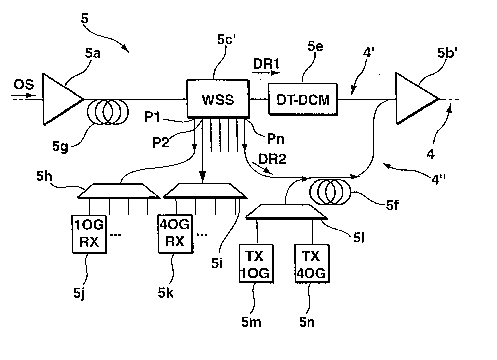
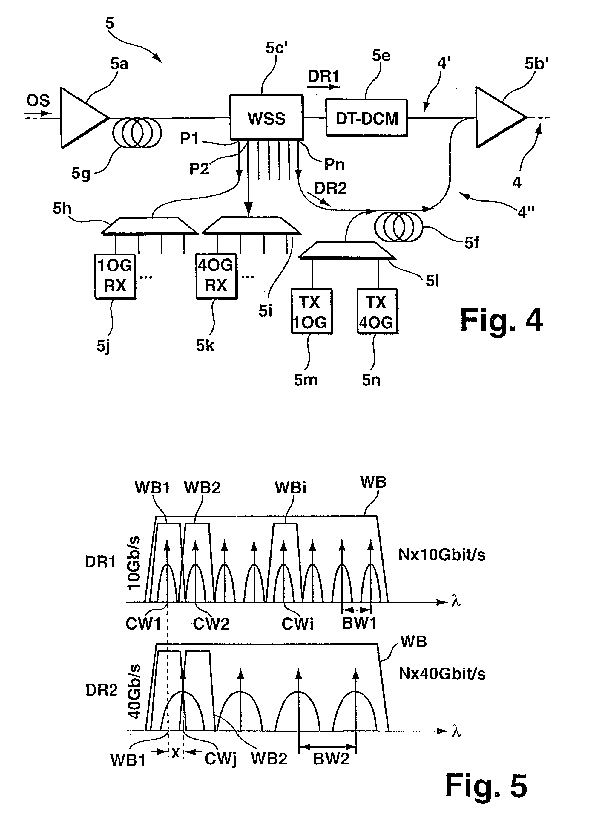
[0039]FIG. 4 shows a more detailed block diagram of the network element 5 in accordance with the present invention, as comprised in the optical transmission system 1 of FIG. 1. Again, elements already described above with reference to appended FIGS. 2 and 3 have been assigned the same reference numerals in FIG. 4. Basically, the embodiment of FIG. 4 is derived from the embodiment previously described with reference to FIG. 3 and further comprises a third dispersion compensating module (DCM) 5g arranged between the input OFA 5a and the band demultiplexing means which in the present embodiment is devised as a wavelength-selective switch (WSS) 5c′. The WSS 5c′ has a number of ports P1, P2, . . . , Pn for outputting wavelength-selected tributary signals of the optical signal OS. Port P1 is connected with a demultiplexing means 5h, and port P2 is connected with a demultiplexing means 5i. In operative connection with demultiplexing means 5h there are provided a number of receiver units 5j...

fifth embodiment

[0047]FIG. 8 shows a block diagram of the network element 5 in accordance with the present invention, as comprised in the optical transmission system 1 of FIG. 1. The embodiment of FIG. 8 is basically similar to that of FIG. 4 described above, and same or similar elements have been assigned the same reference numerals. As explained in connection with FIG. 4, the network element 5 of FIG. 8 comprises a third dispersion compensating module (DCM) 5g arranged between the input OFA 5a and the band demultiplexing means which in the present embodiment is devised as a first optical coupler 5c″. The coupler 5c″ is connected via a second optical coupler 5.c′″ with demultiplexing means 5h and with demultiplexing means 5i. In operative connection with demultiplexing means 5h there are provided a number of receiver units 5j adapted for receiving tributary signals of said first data rate, i.e. 10 Gbit / s, as already explained above with reference to appended FIG. 4. In operative connection with de...


PUM


Abstract

A network element (5) for use in a wavelength division multiplex (WDM) optical transmission system (1). The WDM optical transmission system (1) comprises at least one demultiplexing means (5c) adapted to demultiplex a received WDM signal into constituent wavelength channels carrying tributary signals with at least a first and at least a second data rate (DR1, DR2). The optical transmission system (1) further comprises at least one first dispersion compensating module (5e) connected with the demultiplexing means for receiving constituent wavelength channels carrying tributary signals having said first data rate (DR1). Furthermore, the optical transmission system comprises at least one bypass bypassing the first dispersion compensating module and connected with the demultiplexing means for receiving constituent wavelength channels carrying tributary signals having said second data rate (DR2). In this way, dispersion compensation of said first data rate constituent wavelength channels can be significantly improved while avoiding detrimental effects on said second data rate constituent wavelength channels.

Description

[0001]The invention is based on a priority application EP 06 290 265.5 which is hereby incorporated by reference.TECHNICAL FIELD[0002]The present invention relates to a network element for use in a Wavelength Division Multiplex (WDM) optical transmission system. The present invention also relates to an optical Wavelength Division Multiplex (WDM) optical transmission system. Furthermore the present invention relates to a method of compensating dispersion-related propagation effects of optical wavelength division multiplex (WDM) signals.BACKGROUND OF THE INVENTION[0003]WDM optical signal transmission at a data rate of 10 Gbit's is severely impacted by cross-channel non-linear effects when transmission occurs on low dispersion optical fibre, e.g., having a chromatic dispersion around 4 ps / nm / km or below, which is the case with almost 50% of deployed optical fibre around the world. The main effect to be taken into account in this context is cross-phase modulation (XPM), which is a non-l...

Claims


Application Information

Patent Timeline
Patent Type & Authority Applications(United States)
IPC IPC(8): H04B10/12H04B10/2513
CPCH04B2210/258H04B10/25133
Inventor CHARLET, GABRIELANTONA, JEAN-CHRISTOPHE
Owner ALCATEL LUCENT SAS
Why Eureka
Try Eureka