Closed loop speed control for a pneumatic dental handpiece

a closed loop and handpiece technology, applied in dentistry, dental surgery, medical science, etc., can solve problems such as difficult sterilization, and achieve the effects of less noise, longer life, and less noise during free-running operation

Inactive Publication Date: 2007-08-16
DENTSPLY SIRONA INC
View PDF20 Cites 15 Cited by
  • Summary
  • Abstract
  • Description
  • Claims
  • Application Information

AI Technical Summary

Benefits of technology

[0012]Still another advantage of the present invention is that the tool tips, typically burs and diamonds, will have a longer life. Since the pneumatic motor can operate at a lower speed, the handpiece itself also should have a longer life in addition to generating less noise during free-r

Problems solved by technology

Thus, it does not necessarily rely on “cylindrical rotor of magnetic material” and/or c

Method used


Image

  • Closed loop speed control for a pneumatic dental handpiece
  • Closed loop speed control for a pneumatic dental handpiece

Examples


Embodiment Construction

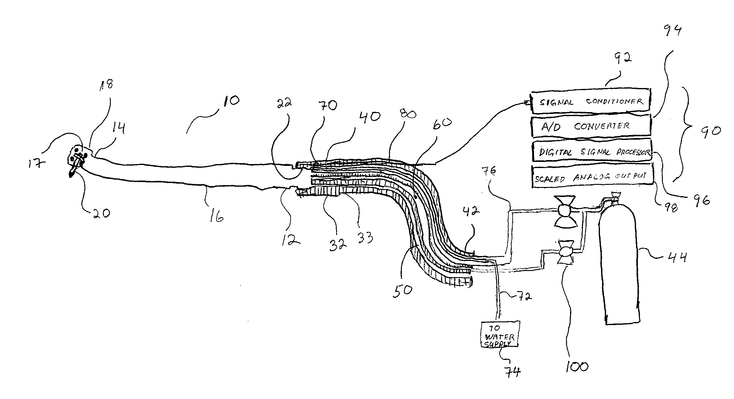
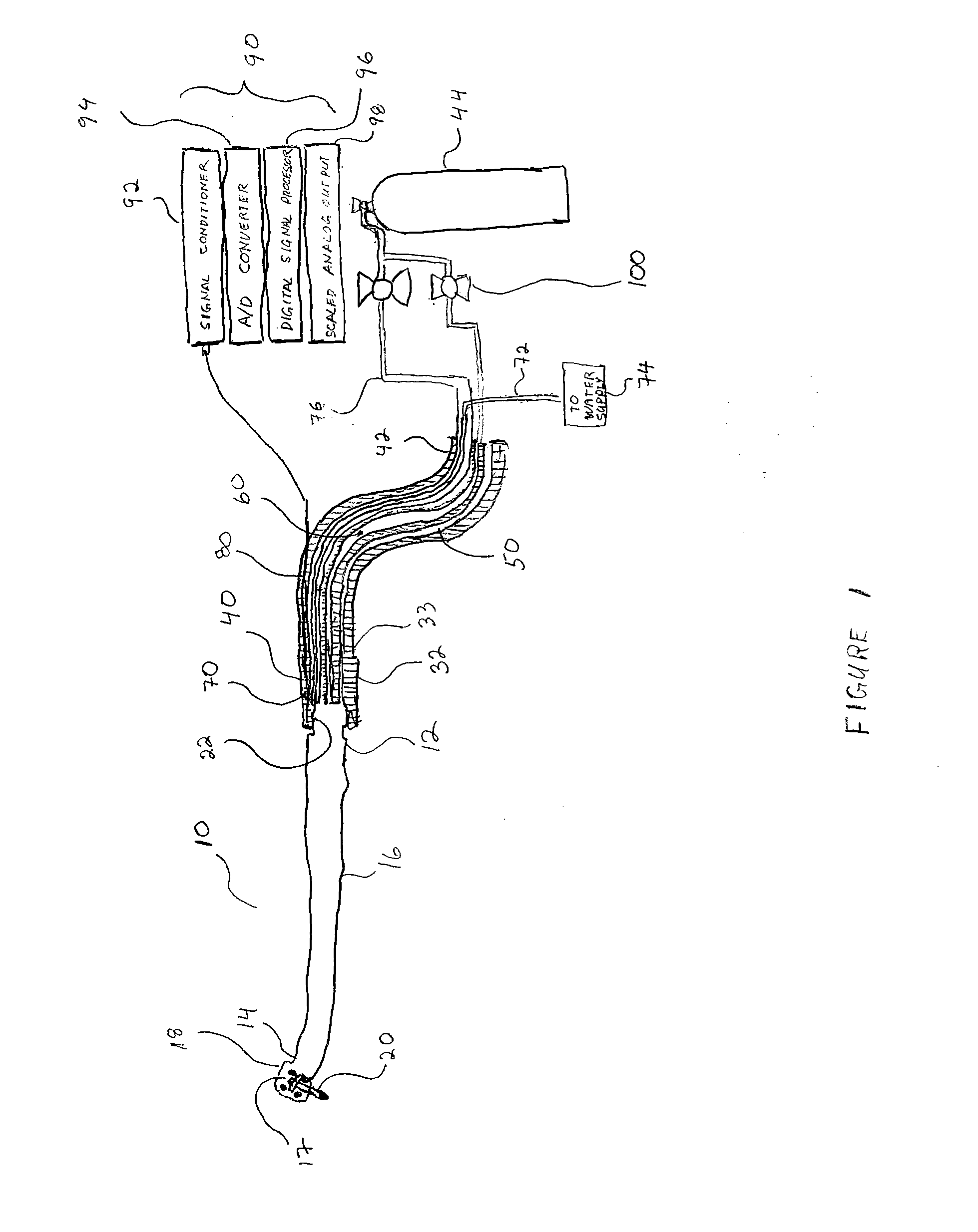
[0015]The present invention comprises a pneumatic dental handpiece 10 coupled to a pneumatic supply hose 40. The dental handpiece 10 has a proximal end 12, a distal end 14 and a body 16 extending between the proximal end 12 and the distal end 14. A handpiece head 18 is located at the distal end 14, the head housing a rotating turbine assembly 17 into which is inserted a bur 20 or tool tip. Bur 20, on assembly into head 18, extends away from the distal end 14 of the handpiece 10. Depending on the handpiece design, the bur can extend substantially parallel to an axis through handpiece 10, the axis extending between the proximal end 12 and the body 16 of the handpiece. The bur may extend substantially perpendicular to this axis. Alternatively, the bur may extend at any angle therebetween. As shown in FIG. 1, the bur extends at an angle to the axis between parallel and perpendicular. The proximal end 12 of the handpiece 10 includes a handpiece coupling 22 designed to interface with a pn...


PUM


Abstract

A detection system for remotely determining the speed of a rotating tool tip in a pneumatic dental handpiece. A means for detecting the speed of the rotating tool tip monitors a periodic mechanical function at the pneumatic hose connected to the handpiece. The monitored periodic mechanical function serves to provide feedback that is used to control the speed of the rotating tool tip. The means for detecting the speed of the rotating tool detects a mechanical function of the rotating tool tip, which in transmitted to a controller. The controller in turn regulates the operation of an air supply valve in response to the detected mechanical function. The valve regulates the flow of air to the handpiece. By continuously adjusting the flow of air through the valve into the pneumatic hose, the speed of the rotating tool is maintained at the desired cutting speed.

Description

FIELD OF THE INVENTION[0001]The present invention is directed to apparatus for controlling the rotational speed of a pneumatic dental handpiece by detecting and monitoring a periodic mechanical function produced by the handpiece.BACKGROUND OF THE INVENTION[0002]In dental treatments with current pneumatic handpieces, a tool tip or burr is rotated at a speed higher than the desired cutting speed. These speeds can be as high as 450,000 revolutions per minute (rpm). When cutting load is applied, this pneumatic system is slowed significantly, adversely affecting cutting capability. The dental practitioner must maintain a useful system speed for cutting by carefully balancing cutting load and pneumatic pressure in order to properly accomplish the cutting operation. Water is also typically provided during the cutting operation to cool the cutting surface as well as the tool surface.[0003]Knowledge of the speed of the rotating burr and / or the rotating turbine under load is desirable and nec...

Claims


Application Information

Patent Timeline
IPC IPC(8): A61C1/02A61C1/05
CPCA61C1/0015A61C1/05A61C1/0038
Inventor BRENNAN, KEVINBECK, TIMOTHY M.NOVAK, EUGENE J.
Owner DENTSPLY SIRONA INC
Why Eureka
Try Eureka