Structured codebook and successive beamforming for multiple-antenna systems

a technology of multiple antennas and codebooks, applied in the field of wireless communications, can solve the problems of significant performance degradation, high complexity of high-rate communication systems, and the increase of the bandwidth of the system, and achieve the effect of low complexity and low feedback ra

Active Publication Date: 2007-08-16
NEC CORP
View PDF20 Cites 253 Cited by
  • Summary
  • Abstract
  • Description
  • Claims
  • Application Information

AI Technical Summary

Benefits of technology

[0012]The present invention is directed to quantized, multi-rank beamforming methods and apparatus. Embodiments of the present invention can considerably outperform known beamforming and precoding techniques

Problems solved by technology

The hostility of the wireless fading environment and channel variation makes the design of high rate communication systems very challenging.
Although perfect CSI is desirable, practical systems are usually built only on estimating the CSI at the receiver, and possibly feeding back the CSI to the transmitter through a feedback link with a very limited capacity.
Partial feedback models have been considered due to the limitations of the feedback channel from the receiver to the

Method used


Image

  • Structured codebook and successive beamforming for multiple-antenna systems
  • Structured codebook and successive beamforming for multiple-antenna systems
  • Structured codebook and successive beamforming for multiple-antenna systems

Examples


Embodiment Construction

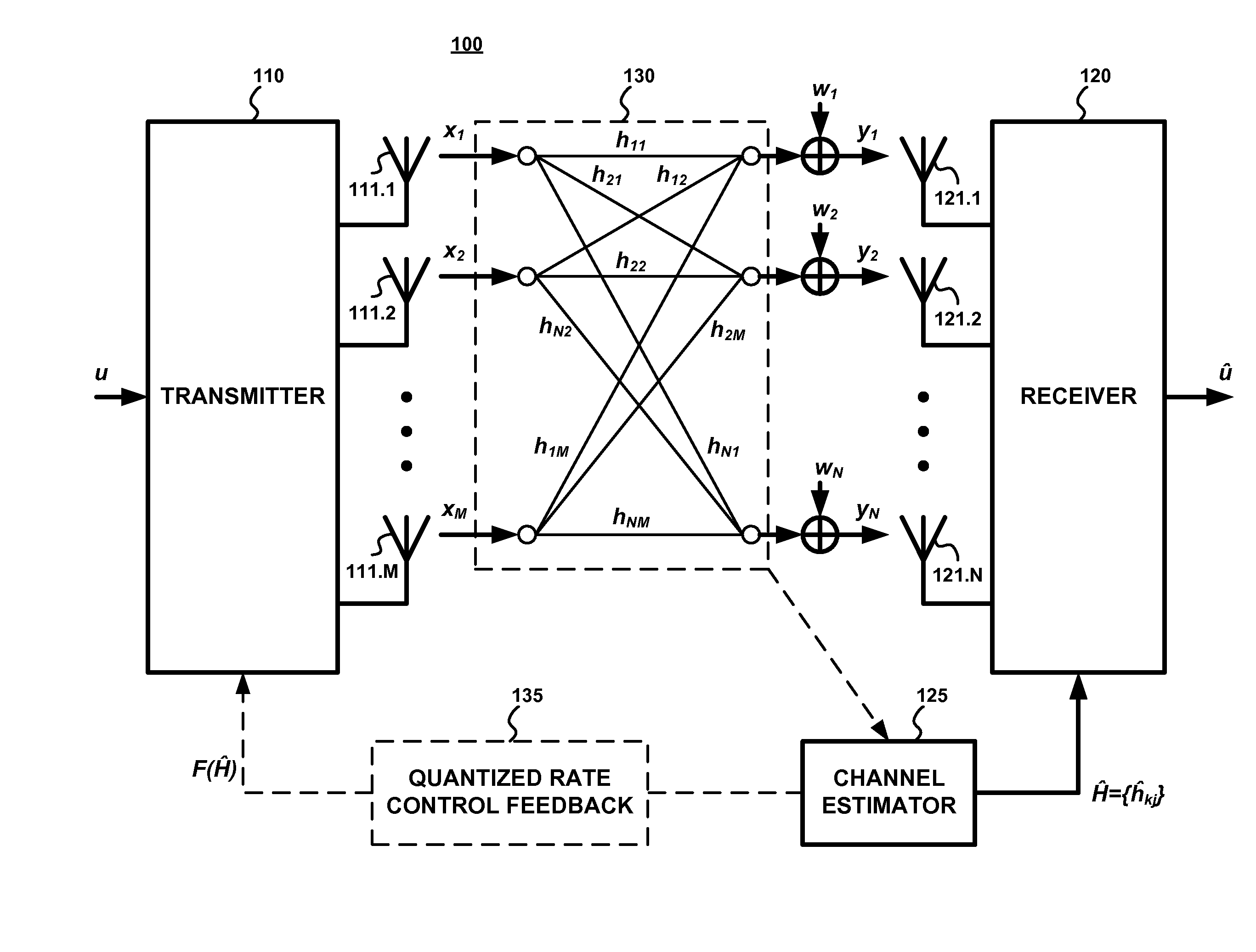
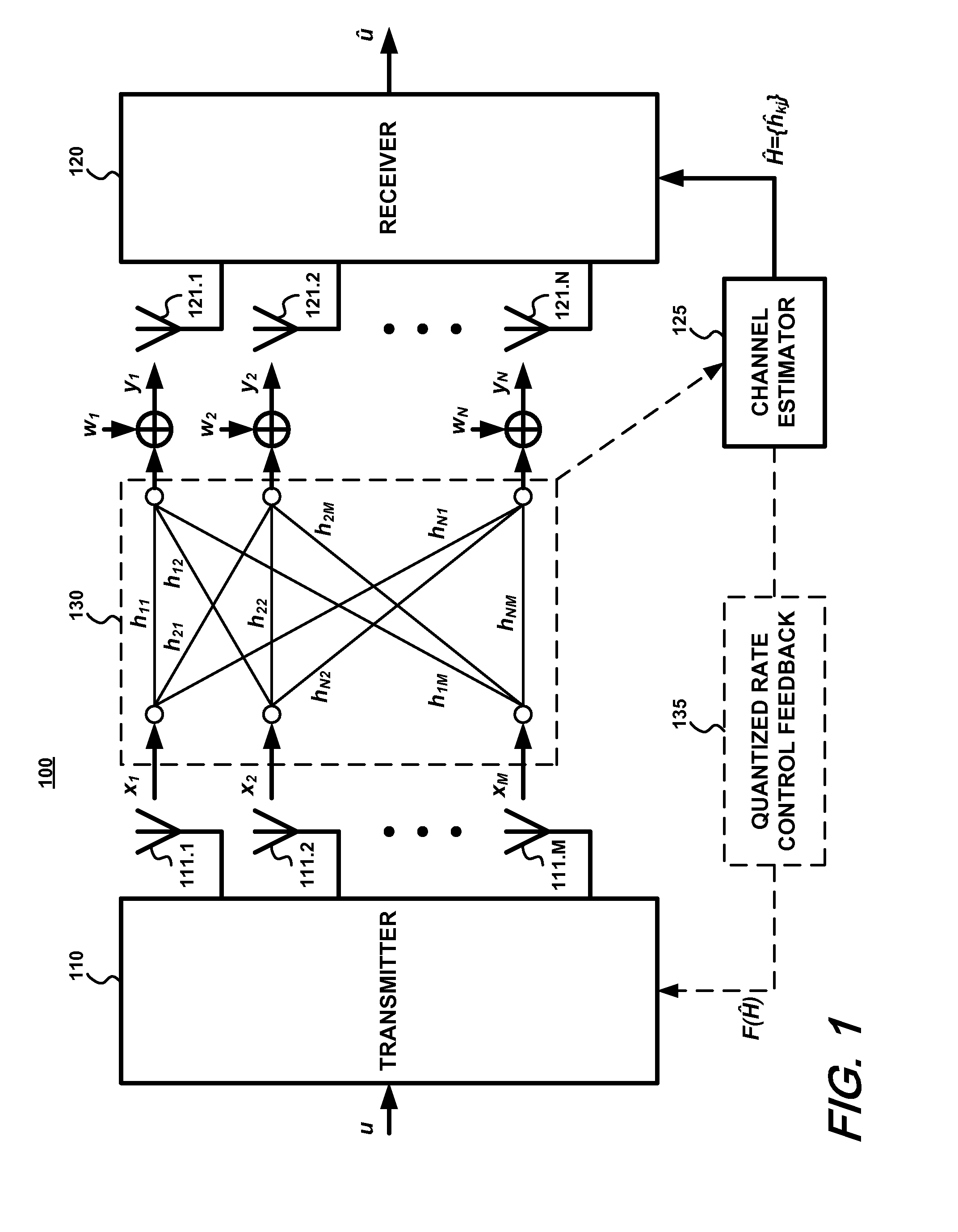
[0032]An exemplary multiple-antenna communication system 100 with quantized feedback is schematically shown in FIG. 1. A transmitter 110 transmits from t transmitting antennas 111.1-111.t over a fading channel 130 to r receiving antennas 121.1-121.r coupled to a receiver 120. A channel estimator 125 provides an estimate of the channel 130 to the receiver 120. The channel estimate is also quantized and provided to the transmitter 110 via a quantized rate control feedback channel 135.

[0033]For purposes of analysis, a flat fading channel model is assumed in which the channel remains constant for each block of transmission. Furthermore, the feedback channel 135 is assumed to be an error-free, zero-delay feedback channel from the receiver to the transmitter, carrying B bits of information about the channel realization every frame.

[0034]For a multiple-antenna system with r receive and t transmit antennas the baseband channel model can be expressed as follows:

Y=HX+W,   (1)

where Y is the r×...


PUM


Abstract

A quantized multi-rank beamforming scheme for multiple-antenna systems such as a multiple-input-multiple-output (MIMO) wireless downlink. User equipment (UE) estimates downlink channel and transmit power and determines rank and power allocations. A quantized beamforming matrix is then determined by the UE using successive beamforming. The UE also determines channel quality indices (CQI) which it feeds-back to the wireless downlink base station along with the index of the quantized beamforming matrix. The base station uses the CQI information to select a UE for scheduling of downlink transmission and the quantized beamforming matrix index received from the selected UE to beamform the downlink transmission to the UE. Base station overhead and is minimized while providing near-optimal performance given the constraints of a limited feed-back channel and computational complexity of the UE.

Description

CROSS REFERENCE TO RELATED APPLICATIONS[0001]This application claims the benefit under 35 U.S.C. §119(e) of U.S. Provisional Application No. 60 / 743,290, filed Feb. 14, 2006, and of U.S. patent application Ser. No. 11 / 554,278, filed Oct. 30, 2006, the entire contents and file wrappers of which are hereby incorporated by reference for all purposes into this application.FIELD OF THE INVENTION[0002]The present invention relates to the field of wireless communications, particularly wireless, high-rate communications using multiple-antenna systems.BACKGROUND INFORMATION[0003]The hostility of the wireless fading environment and channel variation makes the design of high rate communication systems very challenging. To this end, multiple-antenna systems have shown to be effective in fading environments by providing significant performance improvements and achievable data rates in comparison to single antenna systems. Wireless communication systems employing multiple antennas both at the tran...

Claims


Application Information

Patent Timeline
IPC IPC(8): H04B1/02H04M1/00H04B7/02
CPCH04B7/0408H04B7/046H04B7/0456H04W52/42H04B7/0486H04B7/0617H04B7/04H04B7/0413H04W88/02H04W88/08
Inventor KHOJASTEPOUR, MOHAMMAD ALIWANG, XIAODONGMADIHIAN, MOHAMMAD
Owner NEC CORP
Why Eureka
Try Eureka