Expendable turbine driven compression cycle cooling system

a technology of compression cycle and turbine, which is applied in the direction of domestic cooling equipment, refrigeration components, lighting and heating equipment, etc., can solve the problems of limited electric or mechanical shaft power, limited heat sinking, and large cooling requirements

a technology of compression cycle and turbine, which is applied in the direction of domestic cooling equipment, refrigeration components, lighting and heating equipment, etc., can solve the problems of limited electric or mechanical shaft power, limited heat sinking, and large cooling requirements

US20070193301A1Active Publication Date: 2007-08-23HAMILTON SUNDSTRAND CORP

Image

  • Expendable turbine driven compression cycle cooling system
  • Expendable turbine driven compression cycle cooling system
  • Expendable turbine driven compression cycle cooling system

Examples


Embodiment Construction

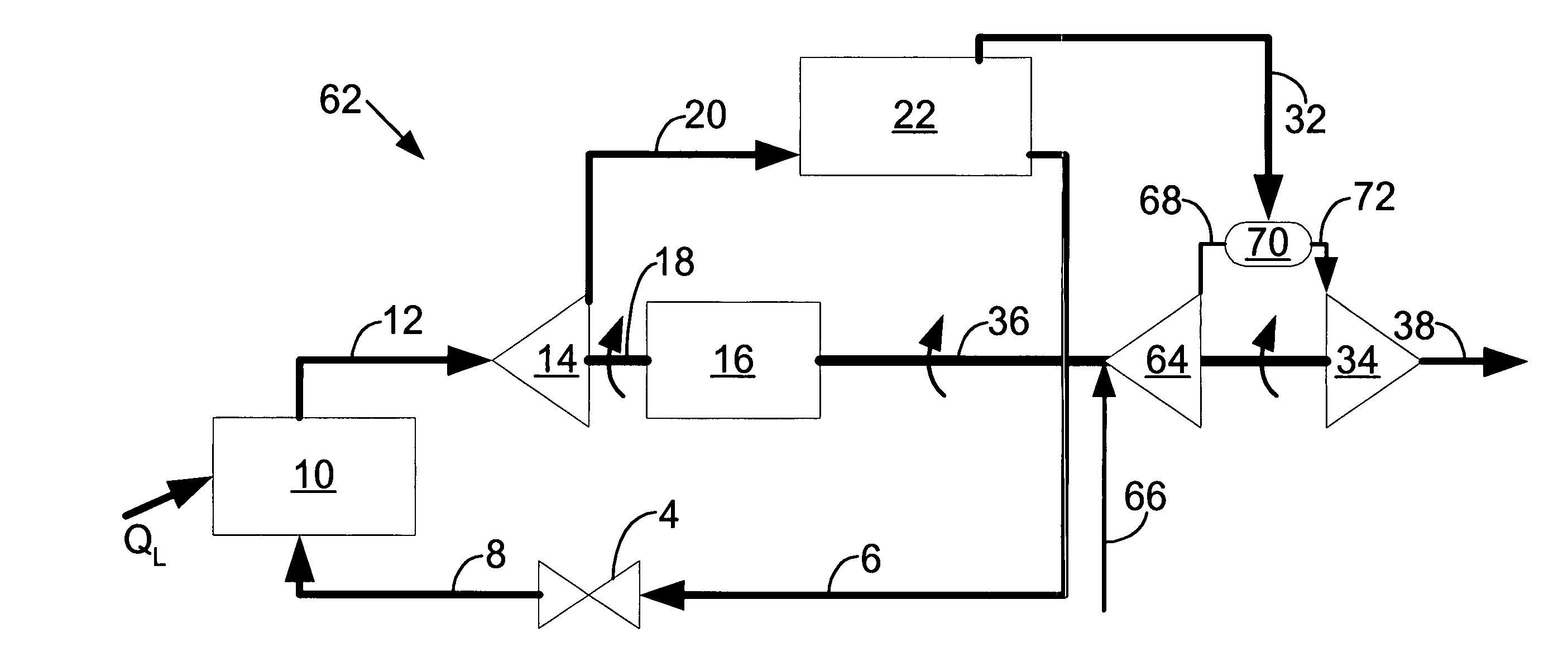
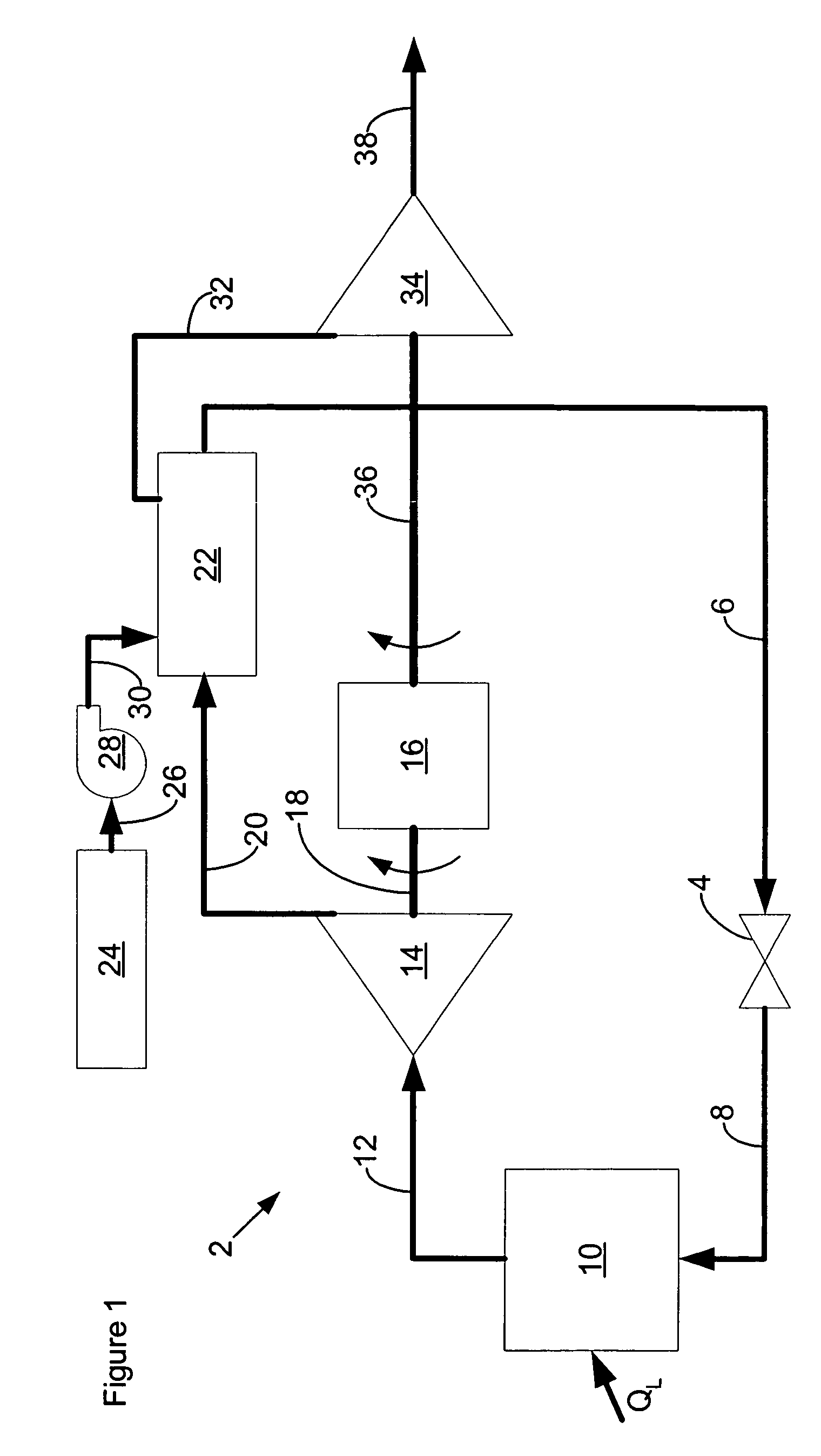
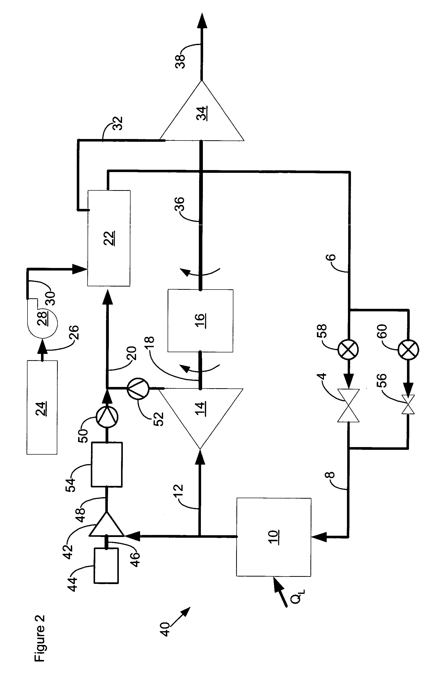
[0010]FIG. 1 is a schematic of an expendable turbine driven vapour compression cycle cooling system 2 according to a possible embodiment of the invention. An expansion valve 4 receives high-pressure working fluid in a liquid state from a high-pressure working fluid supply path 6. The working fluid may comprise any desirable working fluid that has a suitable latent heat or enthalpy of vaporisation and boiling point within a reasonable pressure range for a target application. The expansion valve 4 restricts flow of the liquid working fluid from the high-pressure working fluid supply path 6 into an expansion valve output path 8, thereby reducing pressure of the working fluid in the expansion valve output path 8.

[0011] A-low temperature or cool side heat exchanger 10 receives the low-pressure working fluid from the expansion valve output path 8. It also transfers heat QL from a heat load to the low-pressure working fluid and serves as an evaporator that causes the working fluid to rise...


PUM


Abstract

A cooling system with a compression cooling cycle for a working fluid that passes an expendable fluid through a warm side heat exchanger for the cooling system to cause the expendable fluid to vaporise and thus absorb heat from the working fluid by way of latent heat or enthalpy of vaporisation and then running the vaporised expendable through a turbine that drives a compressor for the cooling system.

Description

FIELD OF THE INVENTION [0001] The invention generally relates to compression cycle cooling systems, and more particularly to both vapour and air cycle cooling systems that utilise an expendable fluid to assist the cooling system cycle. BACKGROUND OF THE INVENTION [0002] Some proposed high energy applications, such as high energy lasers and high speed long-range aircraft, have large cooling requirements with limited available electric or mechanical shaft power and limited available heat sinking for conventional vapour and air compression cycle cooling systems. High-energy laser systems have relatively low efficiencies that cause waste heat to be approximately ten or more times their beam energy. At the same time, they only operate effectively within stringent temperature ranges. High-speed long-range aircraft have large engine and airframe heat loads during the major portions of their flights, thereby consuming the normal capacity of any available fuel heat sink whilst their high spe...

Claims


Application Information

Patent Timeline
23 Aug 2007
Publication
US20070193301A1
IPC
F25B1/00; F25D9/00; F25B39/04
CPC
B64D13/06; B64D2013/0674; F25B1/00; F25B2400/0751; F25B27/00; F25B2341/0661; F25B9/004; F25B41/385
Inventors
ANDRES, MICHAEL J.