Brush-sieve powder-fluidizing apparatus for feeding nano-size and ultra-fine powders

Active Publication Date: 2007-08-23
INNOVATION TECH INC
View PDF12 Cites 21 Cited by
  • Summary
  • Abstract
  • Description
  • Claims
  • Application Information

AI Technical Summary

Benefits of technology

[0013] More particularly, the present powder-fluidizing apparatus and process feeds the aforementioned types of powders by rotating a brush, in contact with a removable sieve plate, around the sieve plate, and sweeping the powder through holes in the sieve plate in order to break up agglomerated particles in the powder and control the feed rate of the powder to the applicator. The powder swept through the holes drops into a fluidizing funnel, where it is subsequently fluidized by being entrained into a carrier gas. The entrained powder and gas then flow through the funnel and into a hose attached to the present apparatus. The hose carries the entrained powder and gas to the applicator. The funnel surface is vibrated to avoid powder build-up on the surface that can break loose and cause pulses of increased material in the powder flow. Ultrasonic waves can be introduced into the funnel to break up any agglomerated particles remaining in the powder before it reaches the applicator.

Problems solved by technology

However, these approaches are designed for fluidizing larger particle sizes (e.g., particles larger than 635 mesh or 20 micrometers) and are not concerned with maintaining a consistent flow over a wide distribution of particle sizes within the fluidized stream.
In conventional powder feeders, ultra-fine powders, including nano-size materials, tend to agglomerate into larger size particles that do not feed uniformly through the feeder and frequently plug the feeder's orifices.
Furthermore, conventional powder feeders don't maintain a constant flow over a wide distribution of powder particle sizes.
These patents use wire loops or scrapers to move the powder across the sieve which works well for soft materials such as baking flour, but metal powders are much more abrasive and will quickly wear out either the sieve or the scraper.
This action tends to cause non-uniformity in the powder feed rate.
None of the aforementioned devices and methods involve brushing dry powder through a sieve plate for the purpose of both breaking up agglomerated powder particles and simultaneously fluidizing these particles into a carrier gas.
U.S. Pat. No. 5,996,855 and U.S. Pat. No 5,314,090 both teach a method for breaking up and dispensing powders by rotating two adjacent brushes at the funnel port of a hopper, however, neither of these patents discloses a method for brushing dry powders through a sieve plate for de-agglomeration and feeding into a fluidizing carrier gas.

Method used


Image

  • Brush-sieve powder-fluidizing apparatus for feeding nano-size and ultra-fine powders
  • Brush-sieve powder-fluidizing apparatus for feeding nano-size and ultra-fine powders
  • Brush-sieve powder-fluidizing apparatus for feeding nano-size and ultra-fine powders

Examples


second embodiment

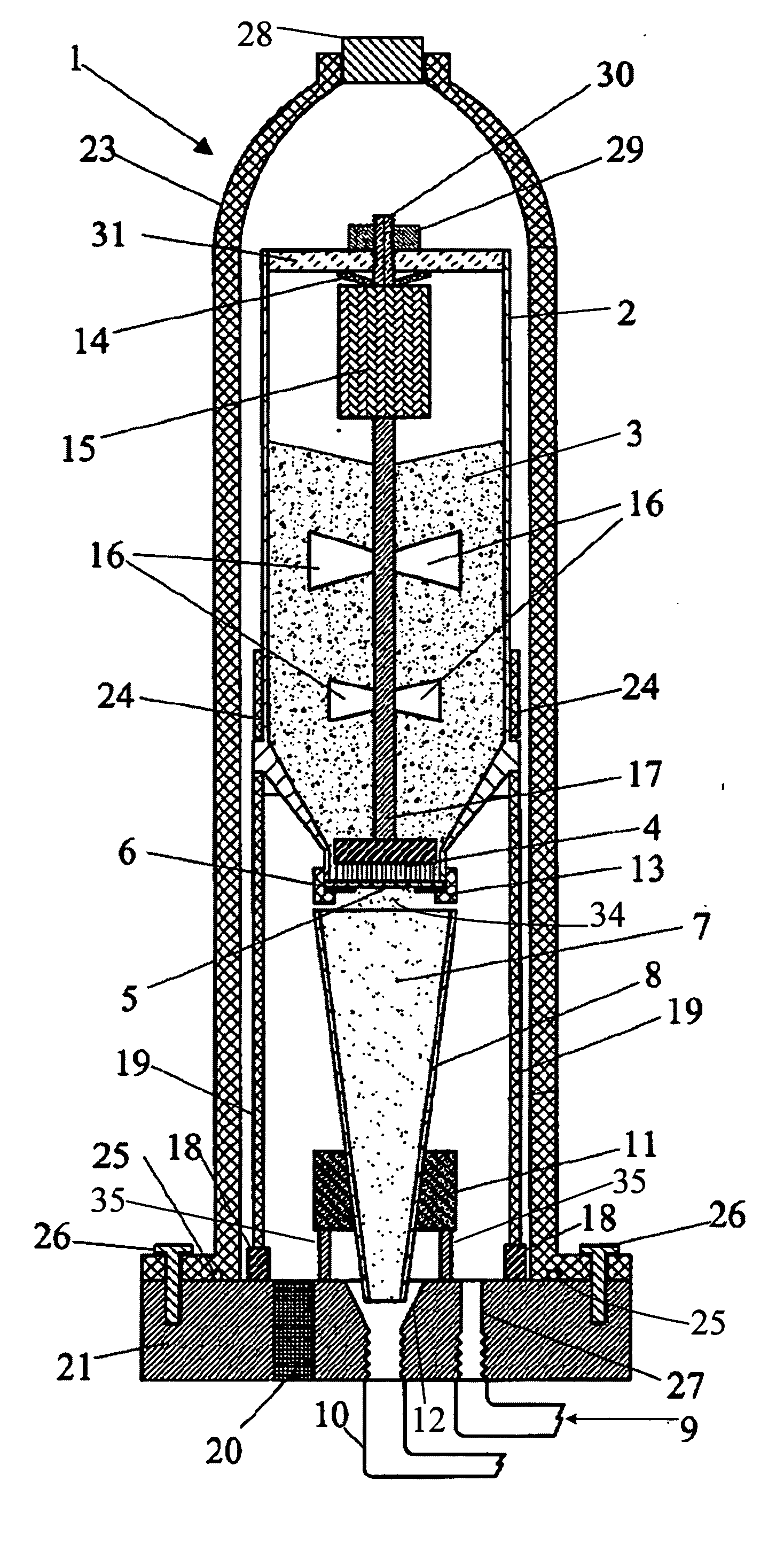
[0024] Referring yet again to FIG. 1, the sieve plate 6 is mounted into a holder 13 which tightens or locks the sieve plate 6 in place to prevent movement of the sieve plate 6 during rotation of brush 4. In the present apparatus 1, the holder 13 permits removal of the sieve plate 6 and installation of an alternate sieve plate 6. This ability to exchange sieve plates 6 permits a new sieve plate 6 to be installed into the apparatus 1 when the existing sieve plate 6 becomes worn.

third embodiment

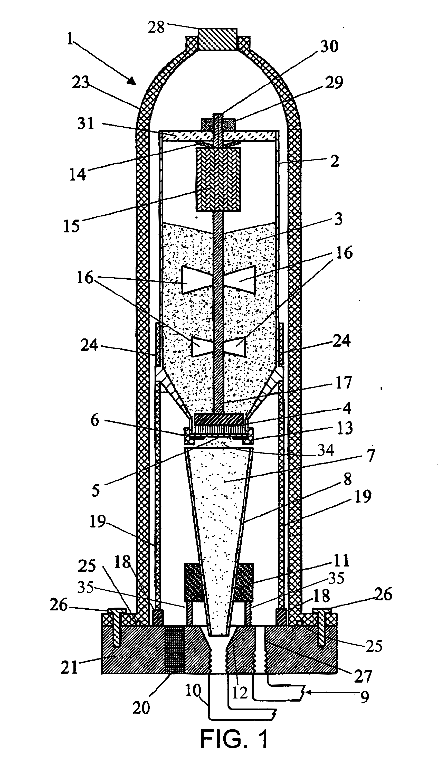
[0025] Referring yet again to FIG. 1, in the present apparatus 1, various sieve plate 6 structures and configurations can be selected for optimum feeding of different types of powders 3. Example variations in sieve plate 6 structures and configurations include variations in hole shape, hole size, hole pattern, and number of holes 5, among others. The sieve plate could be constructed from a wire cloth with various mesh sizes, or from a disc with discrete holes perforated into the disc. By way of further example but not limitation, FIG. 2 shows an exemplary plan view of one possible type of sieve plate 6 that utilizes a wire cloth 32 where the mesh pattern in the cloth 32 provides the holes 5. FIG. 3 shows an exemplary plan view of another possible type of sieve plate 6 that utilizes a perforated disc 33 where the perforations in the disc 33 provide the holes 5. An exemplary construction technique for these example sieve plates 6 is for the wire cloth 32 or the perforated disc 33 to b...

fourth embodiment

[0026] Referring yet again to FIG. 1, in the present apparatus 1, the motor with gearhead assembly 15 is mounted outside the pressure housing 23 and the drive shaft 17 is extended through a rotary seal in the plug 28.


PUM

PropertyMeasurementUnit
Weightaaaaaaaaaa
Forceaaaaaaaaaa
Pressureaaaaaaaaaa

Abstract

A powder-fluidizing apparatus is presented which is applicable to feeding ultra-fine and nano-size powders, and powders with a broad particle size distribution, in a uniform manner over a long period of time. Generally, this is accomplished by using a rotating brush to sweep the powder through holes in a removable sieve plate, which breaks up agglomerated particles in the powder and controls the powder feed rate. The powder then drops from the holes into a funnel, where it is fluidized by being entrained into a carrier gas, and then flows through the funnel out of the apparatus to an applicator. The funnel surface is vibrated to avoid powder build-up on the surface that can break loose and cause pulses of increased material in the powder flow. Ultrasonic waves are introduced into the funnel to break up any agglomerated particles remaining in the powder before it reaches the applicator.

Description

CROSS-REFERENCE TO RELATED APPLICATIONS [0001] This application claims the benefit of a previously filed U.S. provisional patent application Ser. No. 60 / 650,598, filed on Feb. 7, 2005.BACKGROUND [0002] 1. Technical Field [0003] The present invention relates to a powder-fluidizing apparatus and process for feeding ultra-fine powders, including nano-size materials, and for feeding powders with a broad particle size distribution, in a uniform manner over a long period of time. The powders are fed into applicators such as coating and spray forming nozzles and guns. [0004] 2. Background Art [0005] Several approaches currently exist for fluidizing powders. However, these approaches are designed for fluidizing larger particle sizes (e.g., particles larger than 635 mesh or 20 micrometers) and are not concerned with maintaining a consistent flow over a wide distribution of particle sizes within the fluidized stream. [0006] In conventional powder feeders, ultra-fine powders, including nano-si...

Claims


Application Information

Patent Timeline
IPC IPC(8): B65B1/04B65B3/04
CPCB05B7/144B05B15/003B22F3/003B22F2998/00C23C24/04B22F2202/15B22F2202/01B05B15/25
Inventor TAPPHORN, RALPH M.GABEL, HOWARD
Owner INNOVATION TECH INC
Why Eureka
Try Eureka