Variable configuration articulated tracked vehicle

a track and variable configuration technology, applied in the field of tracked vehicles, can solve the problems of not ensuring an optimal path, inability to ensure continuous tensioning of the track, and inability to ensure a perfect ellipse, etc., and achieves the effect of wide control of the center of gravity, easy maintenance, manufacturing and assembly

Active Publication Date: 2007-08-23
CHINA SUPERROBOTICS LTD
View PDF13 Cites 50 Cited by
  • Summary
  • Abstract
  • Description
  • Claims
  • Application Information

AI Technical Summary

Benefits of technology

[0011] There are a number of features of the present invention which are advantageous over the prior art. Specifically, the tensioning mechanism is an improvement over the prior art. As well, the present invention provides a wider range of control over the center of gravity by changing the position of the planetary wheel, as well as impact compliance to free fall. The mechanisms of providing the tensioning mechanism and variation of center of gravity location are simple, easy to maintain, manufacture, and assembly. The mobile robot of the present invention may also include other auxiliary items such as: multi-jointed arm, PTZ camera, automatic communication cable winding, small disrupter weapons, shotgun, x-ray equipment, sockets to connect mission payload sensors, standard sensors, sockets for computer and auxiliary sensor interfaces, pre-programmed motions of the vehicle and arm, and task space control of the arm. The vehicle of the present invention is waterproofed.

Problems solved by technology

One of the challenges with mobile robots is to provide a robot that can ascend and descend stairs, slopes, cross ditches, surmount certain obstacles, and generally operate over rough terrain whether moving forward or backward, turning on spot, etc.
Specifically, in the implementation using a spring-slide-bar mechanism it is impossible to ensure continuous tensioning of the track during the motion of the auxiliary wheel.
This is the result of the arm mechanism design, which can not ensure an optimal path (perfect ellipse) of the planetary wheel.
In addition, the location of the arm does not allow a full rotation of the arm because of interference with the platform pulleys axles.
This reduces the effectiveness of the articulated track whose main purpose is to support motion on rough terrain, stairs, etc.
In the implementation using a gear-sprocket mechanism there are no springs, therefore continuous tensioning of the track is impossible as the track may undergo variations in length due to operating conditions or stresses in directions that are not compensated actively by the track and arm mechanisms.
Furthermore, this transmission mechanism is complicated as it involves six gears, 2 sprockets, and 1 chain, thus raising the cost of manufacturing and lowering the reliability.
Specifically, it has limited variation of the track configuration in one direction only.
It has very limited capability to operate on rough terrain.
It cannot climb stairs because it is impossible to ensure tensioning of the track based on the articulated track mechanism.
The mechanism does not ensure an optimal trajectory (perfect ellipse) of the planetary wheel, as there is no fixed focus of the ellipse.
Further, the six-member planetary wheel mechanism is costly to manufacture and install.
Specifically the location of the centre of gravity cannot be changed adequately during the execution of a task to ensure the stability of the robot.
The control of the location of center of gravity is very limited, with potential consequences such as instability on ascent or descent of steep (45 deg) stairs.
Further, this vehicle's capability to cross wider ditches is somewhat limited relative to the platform length.

Method used


Image

  • Variable configuration articulated tracked vehicle
  • Variable configuration articulated tracked vehicle
  • Variable configuration articulated tracked vehicle

Examples


Embodiment Construction

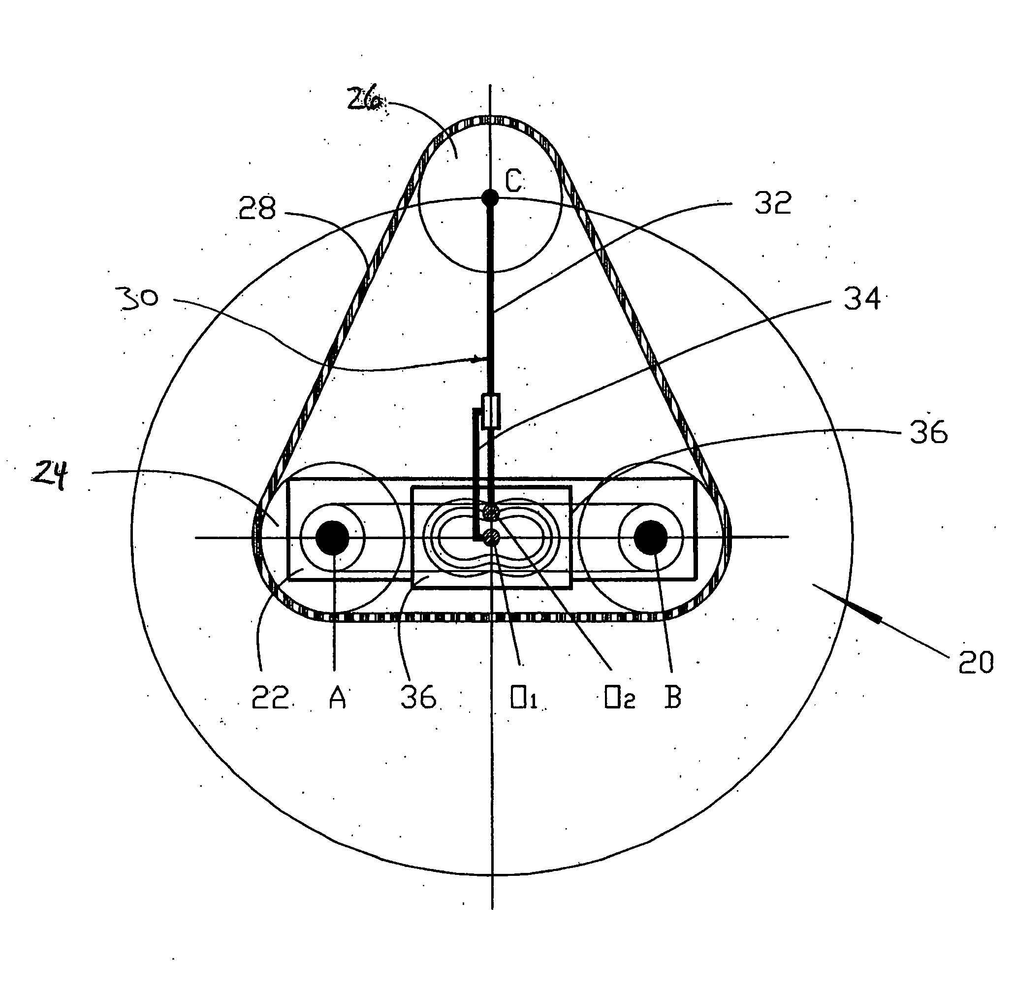
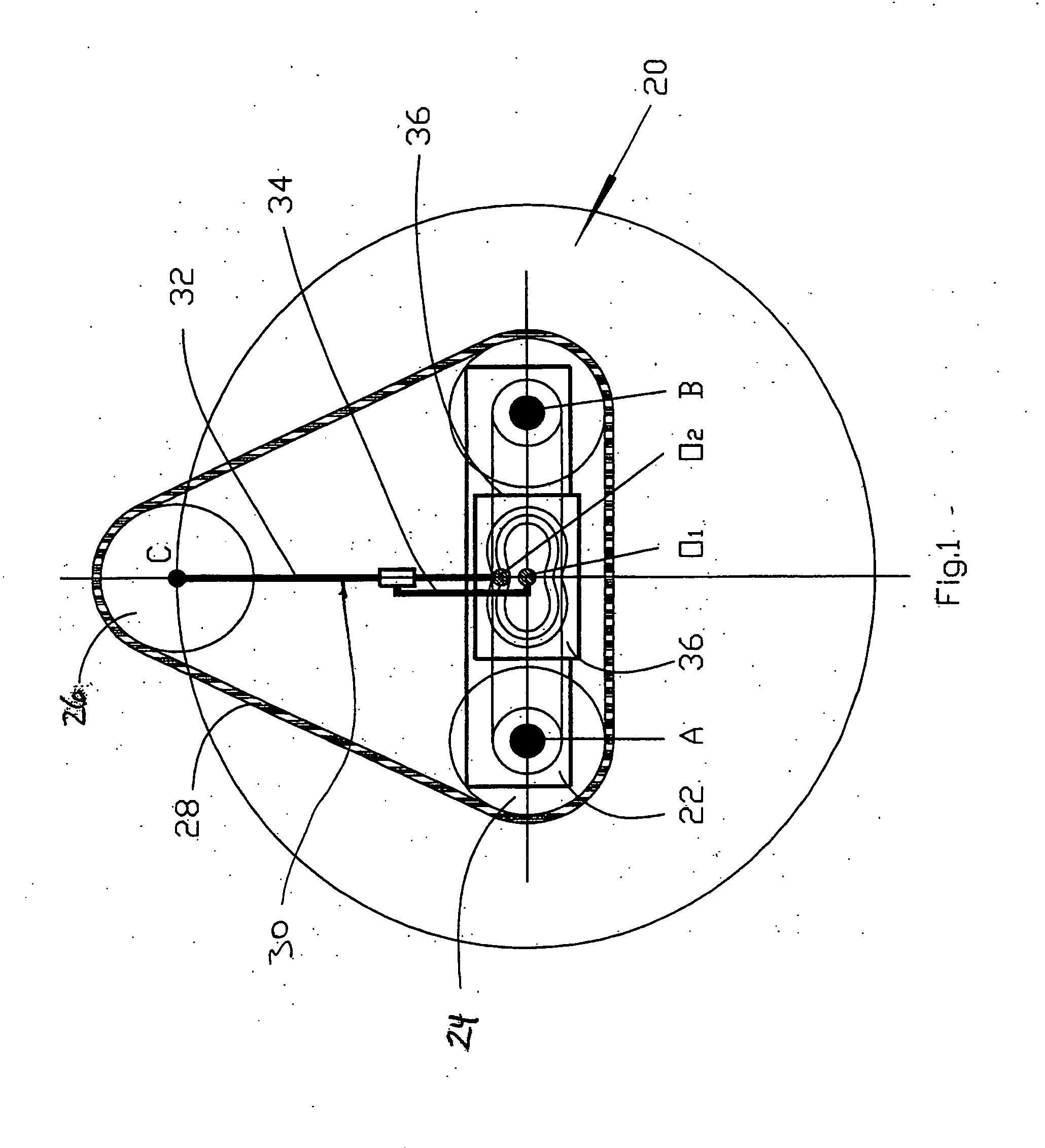
[0044] Referring to the schematic diagram of FIG. 1 the variable configuration articulated tracked vehicle or robot of the present invention is shown generally at 20. Vehicle 20 includes a chassis or platform 22 having pairs of wheels 24 at either end thereof, a pair of planetary wheels 26 and tracks 28. The planetary wheels 26 are each attached to the chassis with a planetary wheel arm 30 which consists of a follower 32, a crank 34 and a fixed cam 36.

[0045] The variable configuration of the tracked vehicle 20 is provided by controlling simultaneously the position of a pair of planetary wheels 26 whose location is controlled precisely by a track configuration-controlling mechanism in the form of a planetary wheel arm 30 described in more detail below. The arm 30 may also include a continuously tension control of the tracks which is described in more detail below.

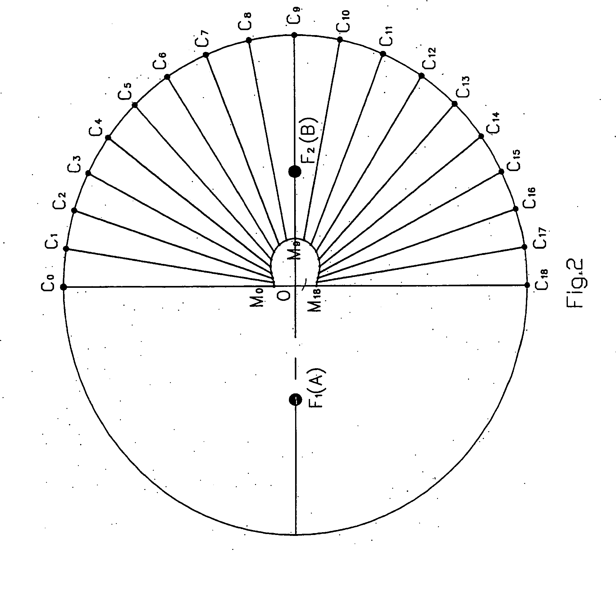
[0046] Referring to FIGS. 1, 2 and 3, the motion trajectory of the center C of the planetary wheel 26 controlled by a pl...


PUM


Abstract

A variable configuration articulated tracked vehicle comprises a chassis, a pair of right and left drive pulleys, a right and left planetary wheel, a right and left track, a right and left arm mechanism, and a right and left drive motor. The drive pulleys are rotatably attached to the chassis and each pair of drive pulleys is in the same plane. The planetary wheels are movable relative to the chassis such that each planetary wheel is in the same plane as its respective drive pulleys. The tracks extend around the pair of drive pulleys and the planetary wheel on the respective sides. The arm mechanisms connect the respective planetary wheel to the chassis. Each arm mechanism is rotatably attached to the chassis with a cam. The cam defines a motion path of one end of the arm whereby the motion of the planetary wheel provides a path for the planetary wheel such that the track path defined by the respective drive pulleys and the planetary wheel is a constant track length. The motors are each operably connected to the respective pair of drive pulleys for driving the track.

Description

CROSS REFERENCE TO RELATED PATENT APPLICATION [0001] This patent application relates to U.S. patent application Ser. No. 11 / 196,486 filed on Aug. 4, 2005 entitled VARIABLE CONFIGURATION ARTICULATED TRACKED VEHICLE which is incorporated herein by reference in its entirety.FIELD OF THE INVENTION [0002] This invention relates to tracked vehicles and in particular an articulated tracked vehicle having multiple configurations. BACKGROUND OF THE INVENTION [0003] Tracked vehicles are well known. They are generally used where the terrain is rough and unpredictable. Tracked vehicles are useful under user control, as well as for partially and fully autonomous mobile robots. One of the challenges with mobile robots is to provide a robot that can ascend and descend stairs, slopes, cross ditches, surmount certain obstacles, and generally operate over rough terrain whether moving forward or backward, turning on spot, etc. [0004] One such mobile robot was suggested in U.S. Pat. No. 4,483,407 which...

Claims


Application Information

Patent Timeline
Patent Type & Authority Applications(United States)
IPC IPC(8): B62D55/00
CPCB62D55/075B62D55/14B62D55/12B62D55/10
Inventor GOLDENBERG, ANDREW A.LIN, JUN
Owner CHINA SUPERROBOTICS LTD
Why Eureka
Try Eureka