Plasma etching methods using nitrogen memory species for sustaining glow discharge

a technology of nitrogen memory species and etching method, which is applied in the direction of electrical equipment, decorative surface effects, decorative arts, etc., can solve the problems of increasing flow rate, affecting the ignition effect of patterned profiles, and maintaining glow discharge during plasma ignition, so as to improve glow discharge ignition characteristics and reduce pressure

Active Publication Date: 2007-08-23
MACRONIX INT CO LTD
View PDF16 Cites 2 Cited by
  • Summary
  • Abstract
  • Description
  • Claims
  • Application Information

AI Technical Summary

Benefits of technology

[0006] The present invention relates, in general, to methods of plasma etching, and more particularly, to methods of plasma etching in which a nitrogen (N2) memory species is formed in the etching chamber. Methods according to the present invention provide improved glow discharge ignition characteristics and allow plasma etching with lower pressures and / or gas flow rates.

Problems solved by technology

While plasma etching offers a valuable tool in performing precise etching of various substrates at the decreased dimensions required by current circuit integration standards, plasma etching suffers from a variety of problems.
One problem in particular is that of maintaining the glow discharge during plasma ignition.
Unfortunately, an associated drawback of using higher pressures and increased flow rates is damage to the patterned profiles.
Inability to maintain the glow discharge, especially in multi-step etching processes, due to reductions in pressure or decreased flow rates leads to significantly decreased process efficiency and increased unit costs.

Method used


Image

  • Plasma etching methods using nitrogen memory species for sustaining glow discharge
  • Plasma etching methods using nitrogen memory species for sustaining glow discharge
  • Plasma etching methods using nitrogen memory species for sustaining glow discharge

Examples


example 1

[0031] In a LAM Model 9400PTX plasma etching apparatus, a substrate having an organic antireflective coating disposed on a surface thereof was placed on the substrate holder of the apparatus. The substrate was then subjected to three separate sets of conditions as shown below in Table 1. In a first “stable” phase, oxygen, helium and N2 are introduced at the flow rates and pressures indicated in Table I with no power applied. In a second phase (1st Substep), the flow of N2 is stopped and a source power of 240 W, at 13.56 MHz is applied to the electrode and 70W at 13.56 MHz is applied to the second (bias) electrode.

TABLE 1N2 Effect (No Plasma)Stable1st Substep2nd SubstepPressure (mt)555Source power (W) (13.56 MHz)0240240Bias Power (W) (13.56 MHz)07070O2 flow (sccm)101010He flow (sccm)404040N2 flow (sccm)10000Backside He pressure (T)888Time (s)˜10-20EP mode5Glow discharge on-rateN / AUp to 100%

[0032] In the Stable step, the reaction gases are allowed to stabilize prior to the applicati...

example 2

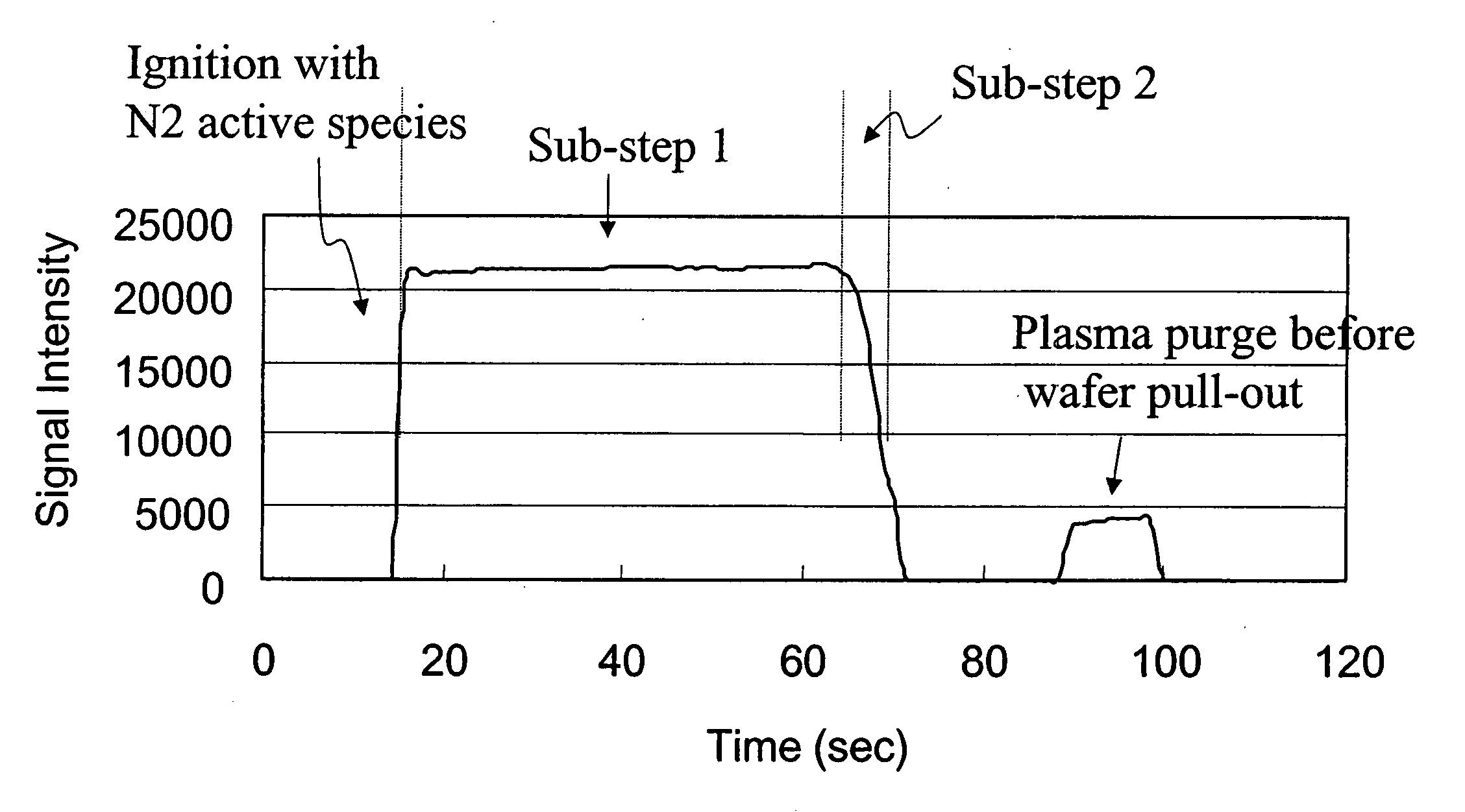
[0033] In a process using the same type of plasma etching apparatus and a similar substrate as Example 1, the substrate was then subjected to four separate sets of conditions as shown below in Table 2. In a first “stable” phase, oxygen, helium and N2 are introduced at the flow rates and pressures indicated in Table 2 with no power applied. In this Example, a separate ignition step is included (independent of the 1st Substep) wherein N2 continues to be introduced while power is applied. A source power of 240 W, at 13.56 MHz is applied to the electrode and 70W at 13.56 MHz is applied to the second (bias) electrode for approximately 3 seconds. The flow of N2 gas into the chamber is then stopped, and the substrate is subsequently etched. “EP mode” refers to endpoint etching wherein the etching occurs until a predetermined endpoint is detected by optical emission spectroscopy (OES).

TABLE 2N2 Memory Effect (Plasma)StableIgnition1st Substep2nd SubstepPressure (mt)5555Source power (W)0240...

example 3

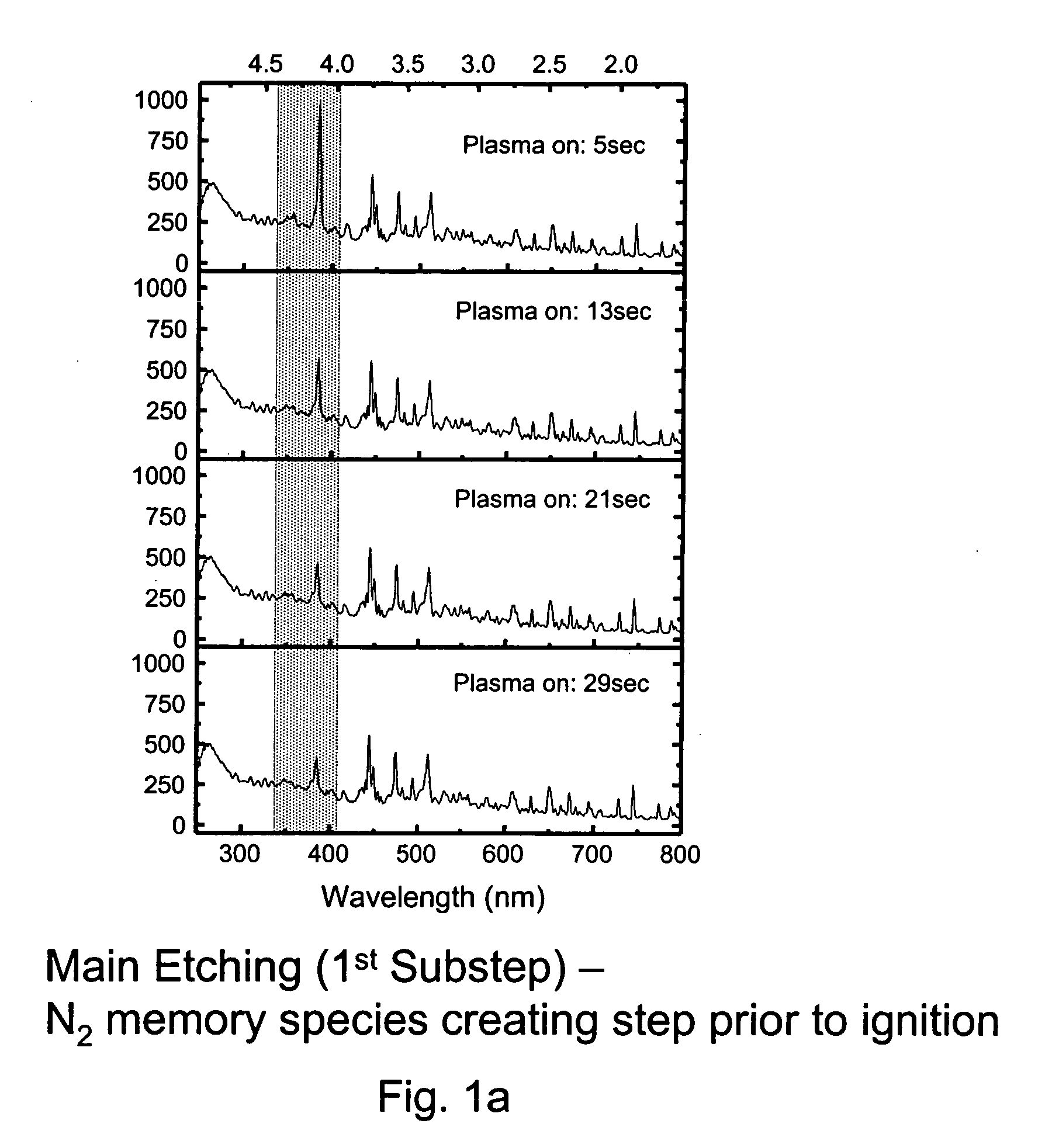
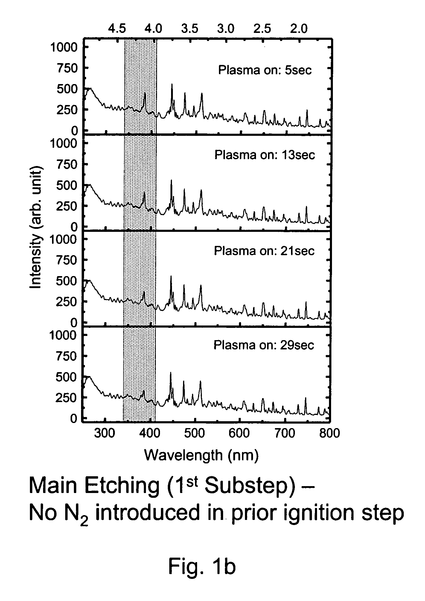
[0035] In a process using the same type of plasma etching apparatus and a similar substrate as Example 1, the substrate was then subjected to five separate sets of conditions as shown below in Table 3. In a first “stable” phase N2 is introduced at the flow rate and pressure indicated in Table 3, with no power applied. A source power of 240 W, at 13.56 MHz is applied to the electrode and 70W at 13.56 MHz is applied to the second (bias) electrode for approximately 3 seconds. The application of power to the electrodes and the flow of N2 gas into the chamber are then stopped for about 20 seconds. During this second stabilizing (Stable-2) step, the reaction gases and other parameters for the main etching steps are allowed to stabilize before applying power. Subsequently, power is applied as indicated in Table 3, and the substrate is etched. As shown in FIG. 1a, the N2 memory species created in the Memory Species Creating Step show a specific signal at 385 nm, and these species persist in...


PUM

PropertyMeasurementUnit
chamber pressureaaaaaaaaaa
pressureaaaaaaaaaa
poweraaaaaaaaaa

Abstract

Methods are described which comprise: providing a plasma etching apparatus having an etching chamber; disposing a substrate to be etched in the chamber; introducing N2 gas and one or more process gases into the chamber; and etching the substrate, wherein the introduction of the N2 gas is stopped prior to etching, and wherein etching comprises an initial plasma ignition wherein at least a portion of the N2 gas remains present in the chamber during initial plasma ignition. Additional methods are described which comprise: providing a plasma etching apparatus having an etching chamber; disposing a substrate to be etched in the chamber; introducing N2 gas and one or more process gases into the chamber; applying power to an electrode in the chamber such that an N2 memory species is formed; and etching the substrate, where the introduction of the N2 gas into the chamber can be stopped prior to etching. Other methods are also described which comprise: providing a plasma etching apparatus having an etching chamber; disposing a substrate to be etched in the chamber; introducing N2 gas into the chamber; applying power to an electrode in the chamber such that an N2 memory species is formed; removing the applied power from the electrode in the chamber; stopping the introduction of the N2 gas into the chamber and introducing one or more process gases into the chamber; and etching the substrate.

Description

BACKGROUND OF THE INVENTION [0001] Dry etching is frequently employed during semiconductor manufacturing for forming structures with small feature sizes. In dry etching, gases are the primary etching medium and the substrate, such as a semiconductor silicon wafer, is etched without wet chemicals (i.e., without etching solutions). During dry etching processes, the material being etched is converted into gas phase materials which are removed from the etching chamber by a vacuum system. [0002] One example of dry etching is plasma etching. Plasma etching utilizes a plasma as the etching medium. Etching plasmas contain many different gaseous species, including ions, free radicals, electrons, photons, neutrals and reaction byproducts. [0003] In one known method of plasma etching referred to parallel plate reaction plasma etching, a process chamber (e.g., the plasma etching chamber) is evacuated and a gas mixture is fed into the chamber and energized to a plasma state using a radio frequen...

Claims


Application Information

Patent Timeline
Patent Type & Authority Applications(United States)
IPC IPC(8): C23F1/00C03C25/68H01L21/302
CPCH01L21/3065
Inventor LEE, HONG-JIHONG, SHIH-PINGWEI, AN-CHYI
Owner MACRONIX INT CO LTD
Why Eureka
Try Eureka