Reactor with packing mean

a technology of liquid gas contact and reactor, which is applied in the direction of lighting and heating apparatus, heating types, separation processes, etc., can solve the problems of high energy consumption and low efficiency, difficult device sound operation, and inability to achieve the chemical reaction to be achieved by liquid gas contact uniformly

Inactive Publication Date: 2007-08-23
NAGAOKA TADAYOSHI
View PDF16 Cites 25 Cited by
  • Summary
  • Abstract
  • Description
  • Claims
  • Application Information

AI Technical Summary

Benefits of technology

[0036] According to this aspect of the invention, in a case where the prior art column packing is replaced by the column packing of this aspect of the invention while a conventional liquid distributor is used, since each of the column packing constituting elements extends vertically in parallel to each other in a non-contact state and in a non-contact state with an inner wall of the device, a drift caused by the contact of the column packing constituting elements with the inner wall of the device can be eliminated and a uniform flow of the liquid can thereby be realized.

Problems solved by technology

The first problem of the prior art column pa-king is that the sheets b constituting the column packing a contact the inner wall c of the column at their folded edges.
Thus, the liquid-gas contact is not performed uniformly and, therefore, chemical reaction to be achieved by the liquid-gas contact is not performed uniformly.
The second problem of the prior art column packing is that, in this column packing a, the oblique disposition of the sheets b causes a large pressure loss which results in a high energy consumption and a low efficiency.
The third problem of the prior art column packing is that increase in the load amount of gas makes a sound operation of the device difficult and, therefore, the upper limit of the load amount of gas has to be held at a relatively low level.
This causes reverse flow of the liquid which should flow down with resulting deterioration in the efficiency of reaction.
Since the liquid distributor is expected to supply the liquid uniformly in the horizontal plane of the column packing, such phenomenon of blowing away of the liquid as droplets must be avoided as reducing the efficiency of the device.
The prior art device has no effective means for preventing such blowing away of liquid droplets in the spaces between the liquid distributor and the column packing and in the space in the vicinity of the liquid collector.
As a result of experiments, however, it has been found that even if the two strand sections m which constitute each liquid supply pipe h are made of the same number of wires, initial flow of the liquid on each of these wires does not necessarily become uniform due to a slight difference in the twisting angle between the wires and difference in affinity of the liquid to the surface of the wires but a flow path is formed in one of the wires which is the easiest wire for the liquid to flow before a flow path is formed in the other wires and the succeeding liquid tends to flow through this initially formed flow path, evading the other wires.
Therefore, the liquid supplied from the liquid distributor to the liquid supply ropes h does not necessarily flow uniformly to the two strand sections m branching from these liquid supply ropes h and, as a result, the liquid does not flow uniformly to the column packing i and a perfect liquid-gas contact cannot be achieved.

Method used


Image

  • Reactor with packing mean
  • Reactor with packing mean
  • Reactor with packing mean

Examples


example

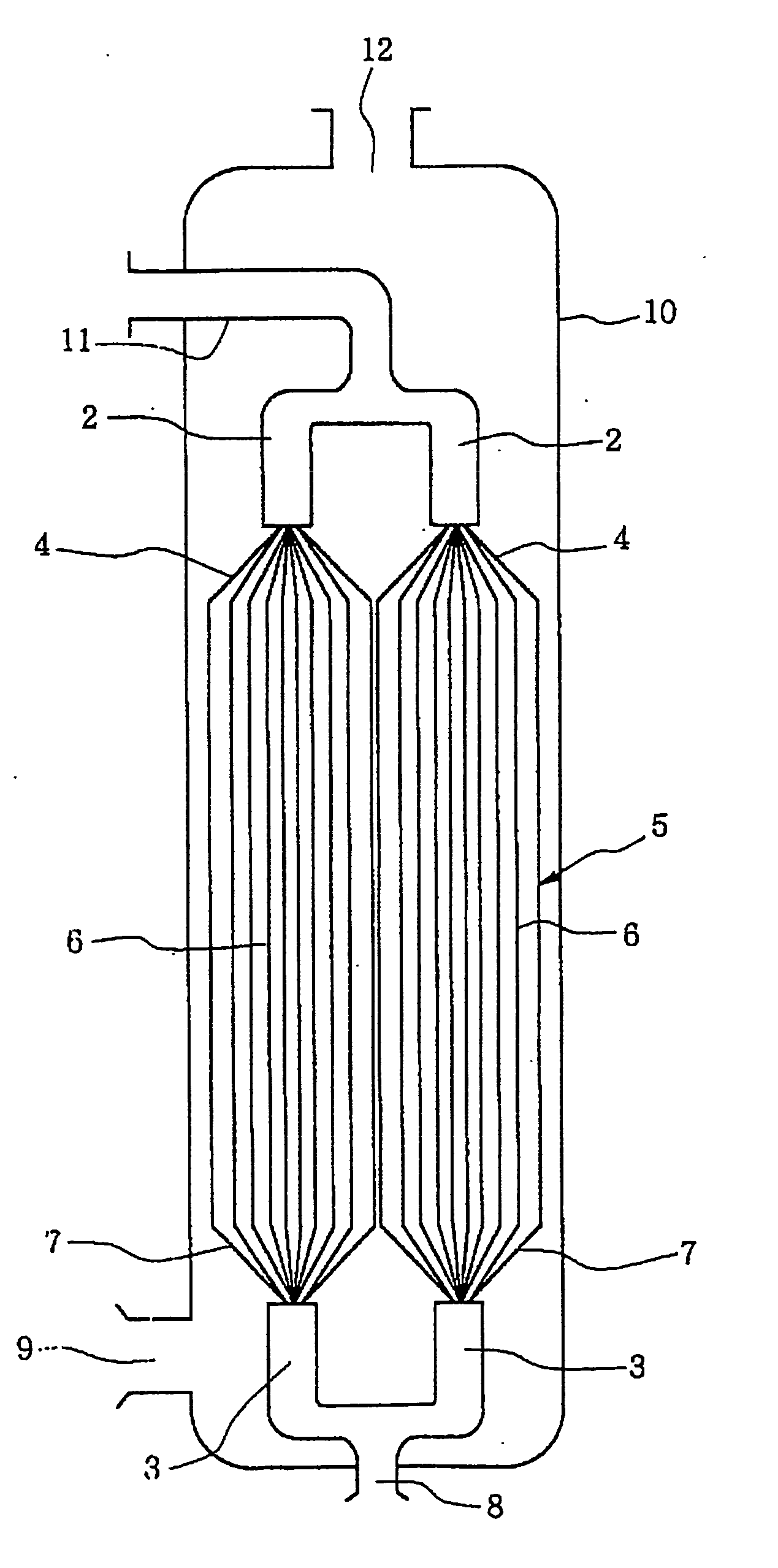
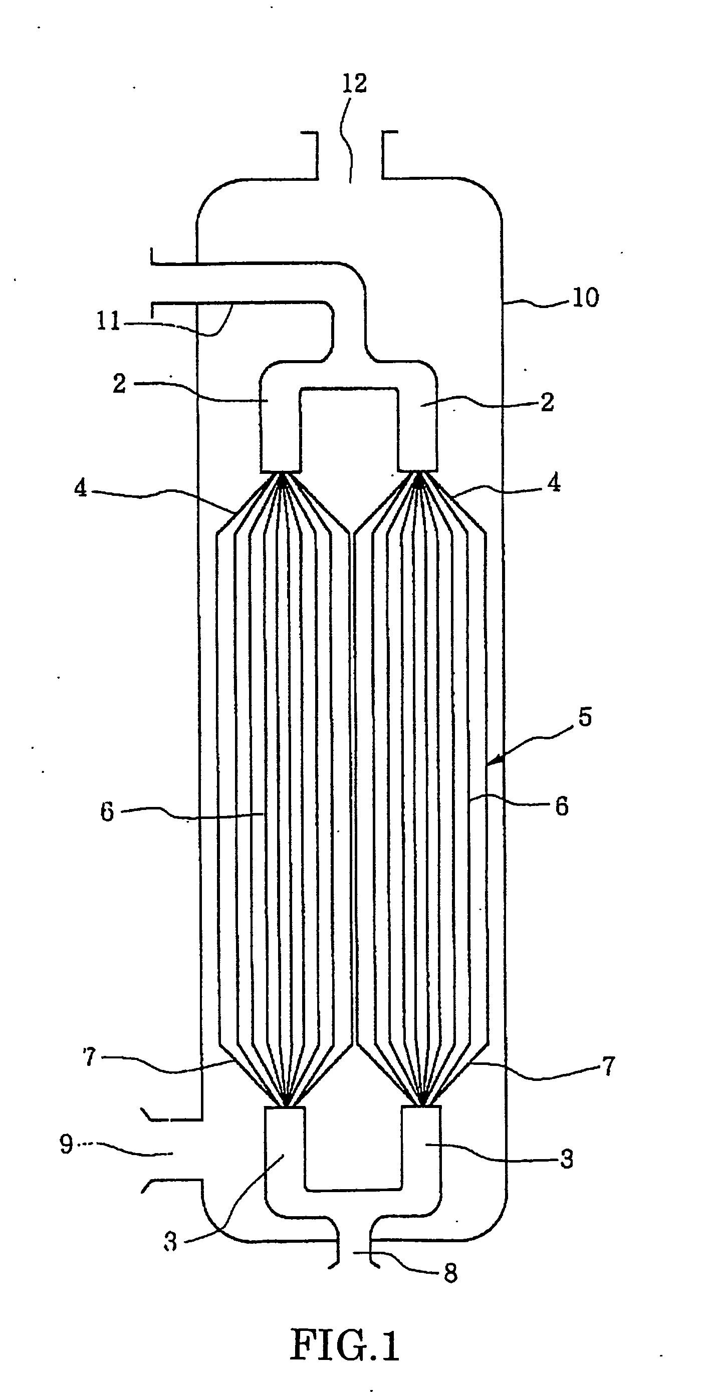
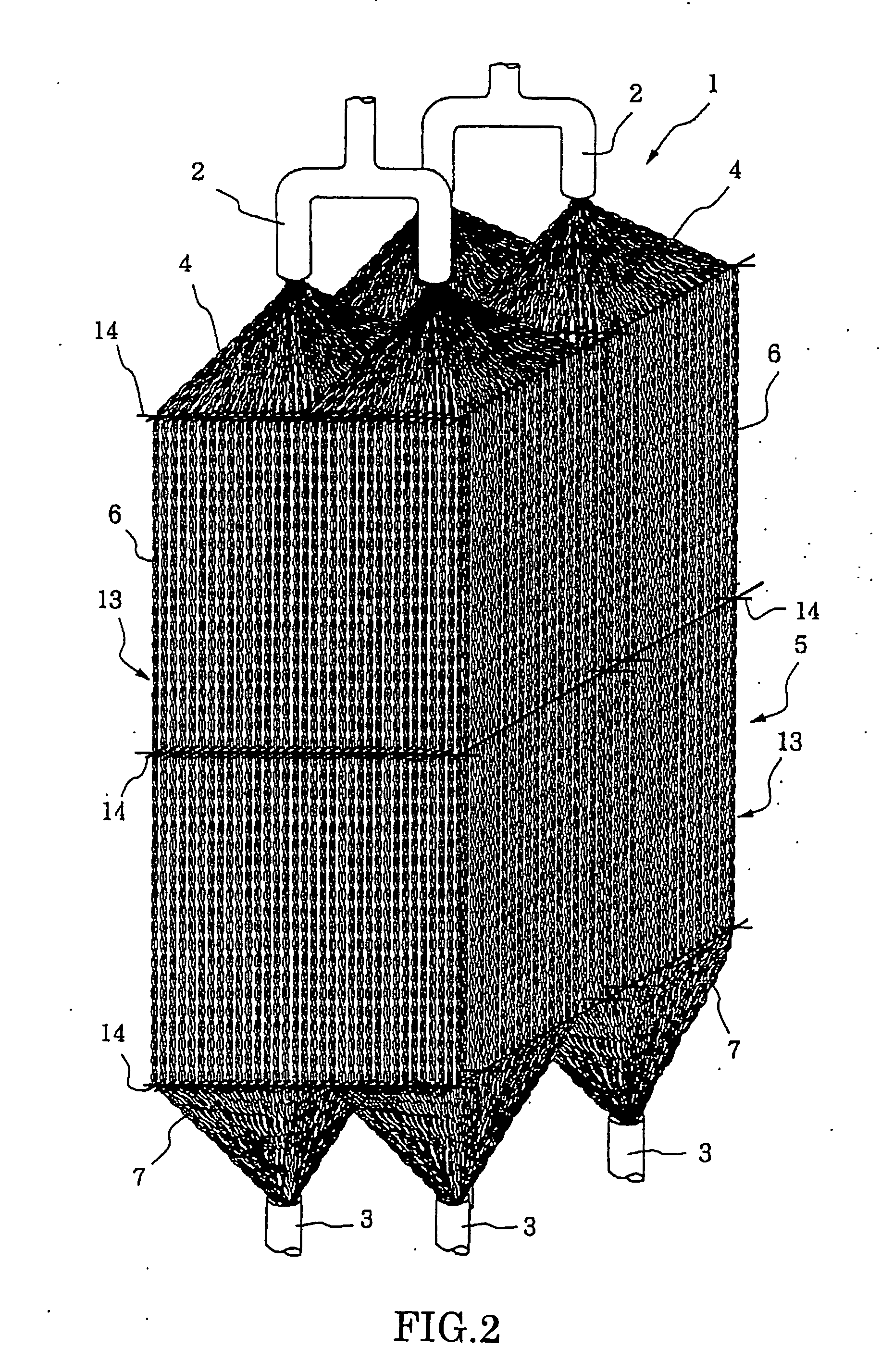
[0093] For confirming the effect of the adaptor of the present invention, the following experiment was made.

[0094] In a vacuum distillation tower, the X-packing shown in Japanese Patent Application Laid-open Publication No. 2001-170475 was filled as a column packing and this X-packing was connected to the liquid distributor provided in the upper portion of the tower by means of the line adaptors 4 shown in FIG. 4 of the present invention. Each adaptor 4 was made by twisting four steel lines each having a diameter of 0.25 mm together to form a single wire and twisting two of these wires together. By using this device, vacuum distillation was conducted with respect to a two-component system of chlorobenzene and ethylbenzene. More specifically, vapor of these two components was blown up from the lower portion of the tower and the vapor reaching the upper portion of the tower was condensed by a condenser. The liquid of the condensed components was distributed from the liquid distributo...


PUM

PropertyMeasurementUnit
diameteraaaaaaaaaa
diameteraaaaaaaaaa
surface areaaaaaaaaaaa

Abstract

There is provided a liquid-gas contact device which has a liquid distributor (2) provided in the upper portion of the device, a liquid collector (3) provided in the lower portion of the device and an internal structure between the liquid distributor (2) and the liquid collector (3) which defines a plurality of flow paths. The liquid-gas-contact device includes a column packing (5) constituting the internal structure made of a plurality of column packing constituting elements (6) each of which extends vertically in parallel to each other in a non-contact state and in a non-contact state with an inner wall of the device, a plurality of adaptors (4) connecting the liquid distributor (2) with the column packing (5) for supplying liquid from the liquid distributor (2) to the column packing (5), and a plurality of collectors (7) connecting the column packing (5) with the liquid collector (3) for supplying liquid from the column packing (5) to the liquid collector (3).

Description

TECHNICAL FIELD [0001] This invention relates to a liquid-gas contact device for a device which, for performing material transfer, heat exchange or mixing between gases, liquids or gas and liquid, has a liquid distributor provided in the upper portion of the device, a liquid collector provided in the lower portion of the device and an internal structure between the liquid distributor and the liquid collector which defines a plurality of flow path. BACKGROUND ART [0002] Known in the art of the liquid-gas contact device of this type is a column packing shown in the partial sectional view of FIG. 23. This column packing a is provided below a liquid distributor in a column and is made of a plurality of corrugated porous sheets laid in layers. These sheets b extend obliquely and are folded at a point at which they contact the inner wall c of the column and extend obliquely again. Liquid which has fallen as droplets from the liquid distributor flows down along these sheets b and wets the ...

Claims


Application Information

Patent Timeline
Patent Type & Authority Applications(United States)
IPC IPC(8): B01D47/00B01D3/00B01J19/32F28F25/02F28F25/08
CPCB01D3/008F28F25/08B01J2219/32206B01J2219/32213B01J2219/3222B01J2219/32227B01J2219/32258B01J2219/32282B01J2219/32289B01J2219/32416B01J2219/32433B01J2219/32458B01J2219/32483F28F25/02B01J19/325
Inventor NAGAOKA, TADAYOSHI
Owner NAGAOKA TADAYOSHI
Why Eureka
Try Eureka