Method and apparatus for generating one or more clock signals for a decision-feedback equalizer using DFE detected data

a technology of dfe detection and clock signals, applied in pulse manipulation, pulse technique, synchronisation signal speed/phase control, etc., can solve problems such as difficult circuit design circuits that operate this fast or very accurate, circuit processing unequalized data that still contains channel impairments, and signal arriving at a receiver is typically corrupted

Active Publication Date: 2007-08-23
AVAGO TECH INT SALES PTE LTD
View PDF0 Cites 86 Cited by
  • Summary
  • Abstract
  • Description
  • Claims
  • Application Information

AI Technical Summary

Benefits of technology

[0006] Generally, methods and apparatus are provided for generating one or more clock signals for a decision-feedback equalizer using DFE detected data. According to one aspect of the invention, a received signal is sampled using a data clock and a transition clock to generate a data sample signal and a transition sample signal. A DFE correction is obtained for each of the data sample and transition sample signals to generate DFE detected data and a DFE transition data. The DFE detected data and DFE transition data are then applied to a phase detector that generates a signal to adjust a phase of one or more of the data clock and transition clock. In one embodiment, an output of the phase detector is applied to a clock and data recovery (CDR) circuit that generates the data and transition clocks. The phase detector can be embodied, for example, as a bang-bang phase detector or a multi-level oversampled phase detector.

Problems solved by technology

Signals arriving at a receiver are typically corrupted by intersymbol interference (ISI), crosstalk, echo, and other noise.
At very high data rates, however, it is difficult to design circuits that operate this fast or to make them very accurate.
Thus, the CDR circuit processes unequalized data that still contains channel impairments.

Method used


Image

  • Method and apparatus for generating one or more clock signals for a decision-feedback equalizer using DFE detected data
  • Method and apparatus for generating one or more clock signals for a decision-feedback equalizer using DFE detected data
  • Method and apparatus for generating one or more clock signals for a decision-feedback equalizer using DFE detected data

Examples


Embodiment Construction

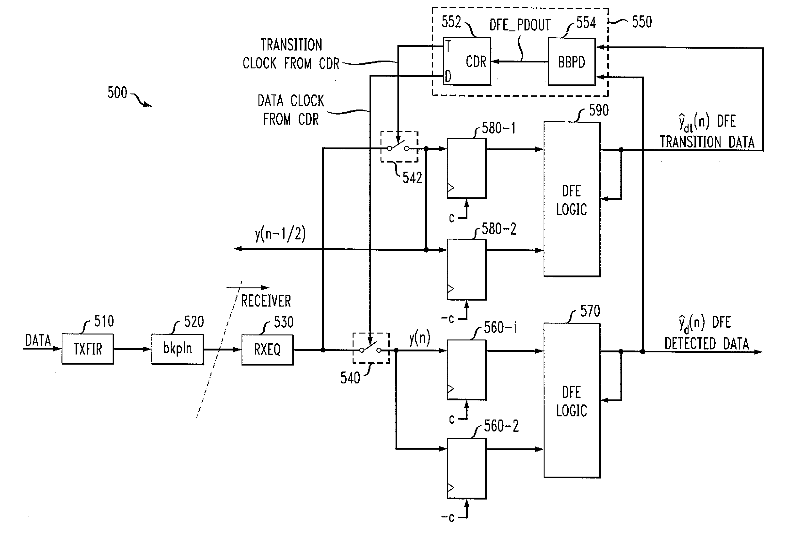
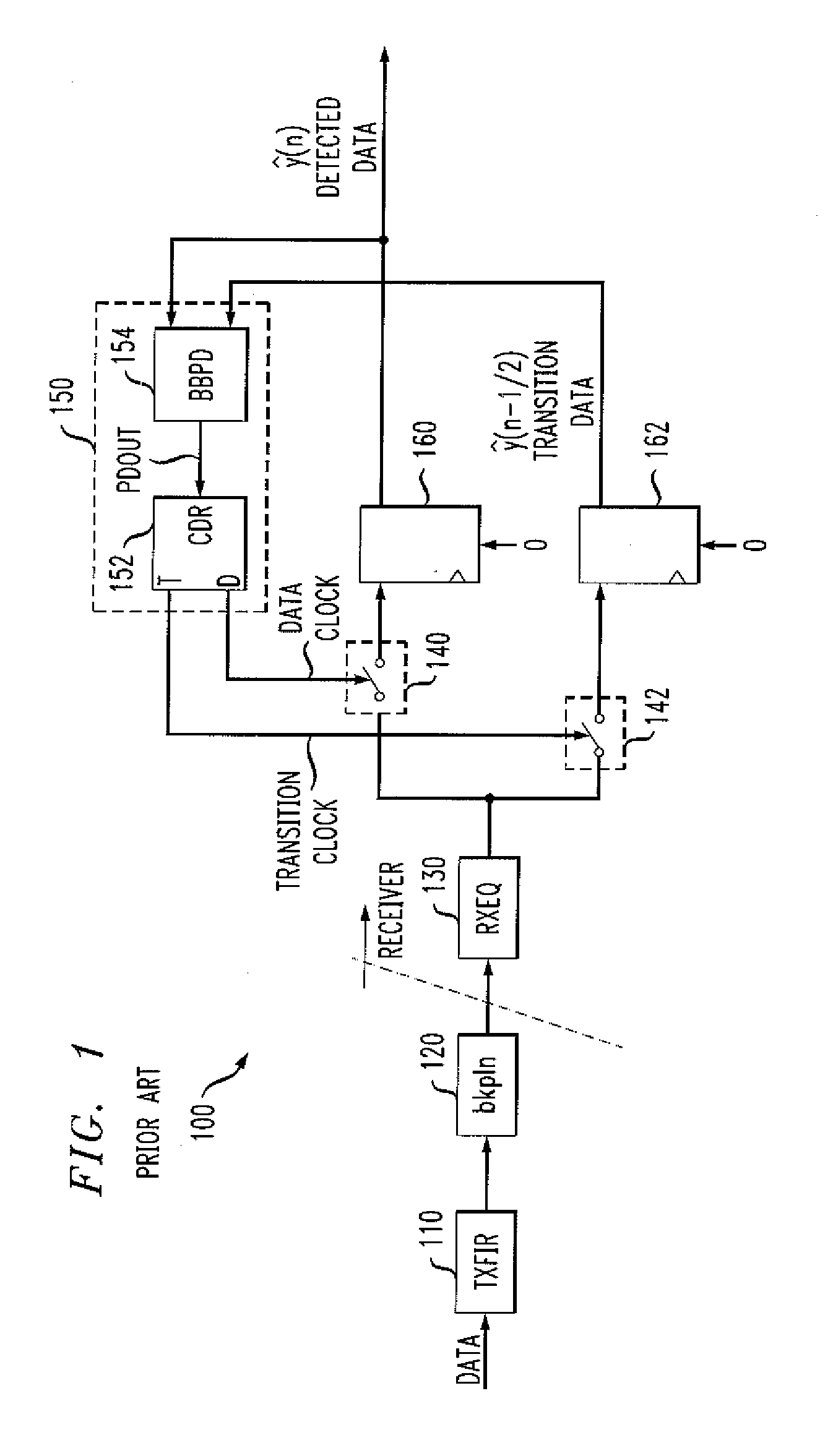
[0019] The present invention provides methods and apparatus for generating one or more clock signals for a decision-feedback equalizer using DFE detected data. FIG. 1 is a block diagram of a conventional serializer / deserializer communication channel 100 having a channel impairment that is due, for example, to a physical transmission medium, such as a backplane or drive head in a magnetic recording system. In the exemplary implementation shown in FIG. 1, the data is transmitted through a backplane channel 120 after optionally being equalized or filtered through a transmit FIR filter (TXFIR) 110. After passing though the backplane 120, the analog signal may optionally be filtered or equalized by a receive equalizer (RXEQ) 130 which may consist, for example, of a continuous time filter. The analog signal out of the RXEQ 130 is sampled at the baud rate by a switch 140 using a sampling clock generated by a clock / data recovery (CDR) circuit 150. A data detector 160 (or a slicer) digitizes...


PUM


Abstract

Methods and apparatus are provided for generating one or more clock signals for a decision-feedback equalizer using DFE detected data. A received signal is sampled using a data clock and a transition clock to generate a data sample signal and a transition sample signal, respectively. A DFE correction is obtained for each of the data sample and transition sample signals to generate DFE detected data and a DFE transition data. The DFE detected data and DFE transition data are then applied to a phase detector that generates a signal to adjust a phase of one or more of the data clock and transition clock. In a multi-level implementation, the received signal is sampled using a clock associated with each of the levels and the samples are latched using a vertical slicing technique to generate DFE data associated with each of said levels.

Description

CROSS-REFERENCE TO RELATED APPLICATIONS [0001] The present application is related to U.S. patent application entitled “Method and Apparatus for Adaptively Establishing a Sampling Phase for Decision-Feedback Equalization,” filed contemporaneously herewith and incorporated by reference herein.FIELD OF THE INVENTION [0002] The present invention relates generally to decision-feedback equalization techniques, and more particularly, to techniques for generating one or more clock signals for a decision-feedback equalizer using DFE detected data. BACKGROUND OF THE INVENTION [0003] Digital communication receivers must sample an analog waveform and then reliably detect the sampled data. Signals arriving at a receiver are typically corrupted by intersymbol interference (ISI), crosstalk, echo, and other noise. Thus, receivers must jointly equalize the channel, to compensate for such distortions, and decode the encoded signals at increasingly high clock rates. Decision-feedback equalization (DFE...

Claims


Application Information

Patent Timeline
Patent Type & Authority Applications(United States)
IPC IPC(8): H03H7/30H04L7/00
CPCH04L7/0062H04L2025/0349H04L7/04H04L7/033
Inventor AZIZ, PERVEZ M.SHEETS, GREGORY W.SMITH, LANE A.
Owner AVAGO TECH INT SALES PTE LTD
Why Eureka
Try Eureka