
System and method for high quality AVC encoding

a high-quality, avc technology, applied in the field of video encoding, to achieve the effect of good motion estimation capability, good visual fidelity, and good quality

Inactive Publication Date: 2007-08-23
SONY CORP +1
View PDF27 Cites 68 Cited by
  • Summary
  • Abstract
  • Description
  • Claims
  • Application Information

AI Technical Summary

Benefits of technology

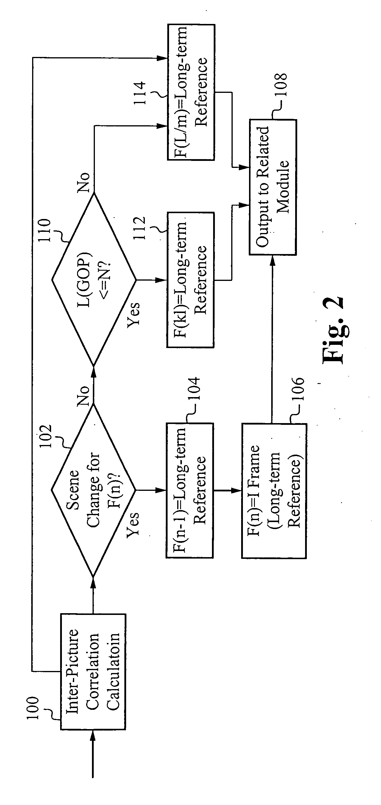
[0017] A coding system utilizes a moderate bit-rate to address the aforementioned problems related to low bit-rate and high bit-rate. Further, it is observed that the initial reference quality influences the subsequent prediction quality significantly. Considering the good motion estimation capability of AVC, if very good visual fidelity is kept in the I-frame, it is possible to propagate the good quality to the subsequent P-frames and B-frames. Instead of using more bits on the foreground objects and fewer bits on the background area, as in the prior art, the coding system significantly improves the visual quality of the background using a long term look-behind prediction. In contrast to using previous frames as the reference predictor for a current frame, an accurate prediction is obtained by using a long term look-behind reference frame that follows the current frame.
[0018] In conventional bit-rate control schemes, a fixed bit-rate ratio is maintained between the I-frame and the P-frame. In contrast, embodiments of the coding system are configured to reduce the quantization scale of the I-frame, thereby improving the visual quality of the P-frames and B-frames, while maintaining the same bit-rate. In this manner, more details are shown in the P-frames and B-frames and the I-frame refresh phenomenon is reduced.
[0019] Embodiments of the coding system also utilize the long term look-behind reference frame as a long term memory motion compensation prediction scheme to effectively handle uncovered areas, also called uncovered objects, in the background. Use of such a prediction scheme compensates for blurring of uncovered objects in the P-frames and B-frames between I-frames. Long term memory motion compensated prediction extends the spatial displacement vector (MV) utilized in macroblock-based hybrid video coding by a variable time delay, thereby permitting the use of more frames than the previously decoded frame for motion compensation. Improvements are expected due to repetition of image sequence content such as covered and uncovered objects, shaking of camera back and forth, etc. Additionally, improvements are obtained when macroblocks in long term memory are coincidentally similar to the current macroblock.
[0020] In most cases, for a given video sequence, an uncovered object in the current frame also appears in subsequent frames. Typically, the uncovered object is observed in subsequent frames for a given time period, such as ½ second, before it is covered again or moved out of frame. As such, most uncovered objects can be matched to known areas in subsequent frames. Utilization of the B-frame improves performance because the B-frame uses information from the subsequent P-frame to reconstruct a picture. The issue is how to construct the P-frame since the P-frame is predicted from earlier frames, not a subsequent frame. If there is not a good prediction for the P-frame, then a good prediction match for the B-frame can not be obtained. The coding system uses the long term look-behind reference frame as a predictive reference that can be used to construct the P-frame.

Problems solved by technology

The issue is how to construct the P-frame since the P-frame is predicted from earlier frames, not a subsequent frame.

Method used


Image

  • System and method for high quality AVC encoding
  • System and method for high quality AVC encoding
  • System and method for high quality AVC encoding

Examples


Embodiment Construction

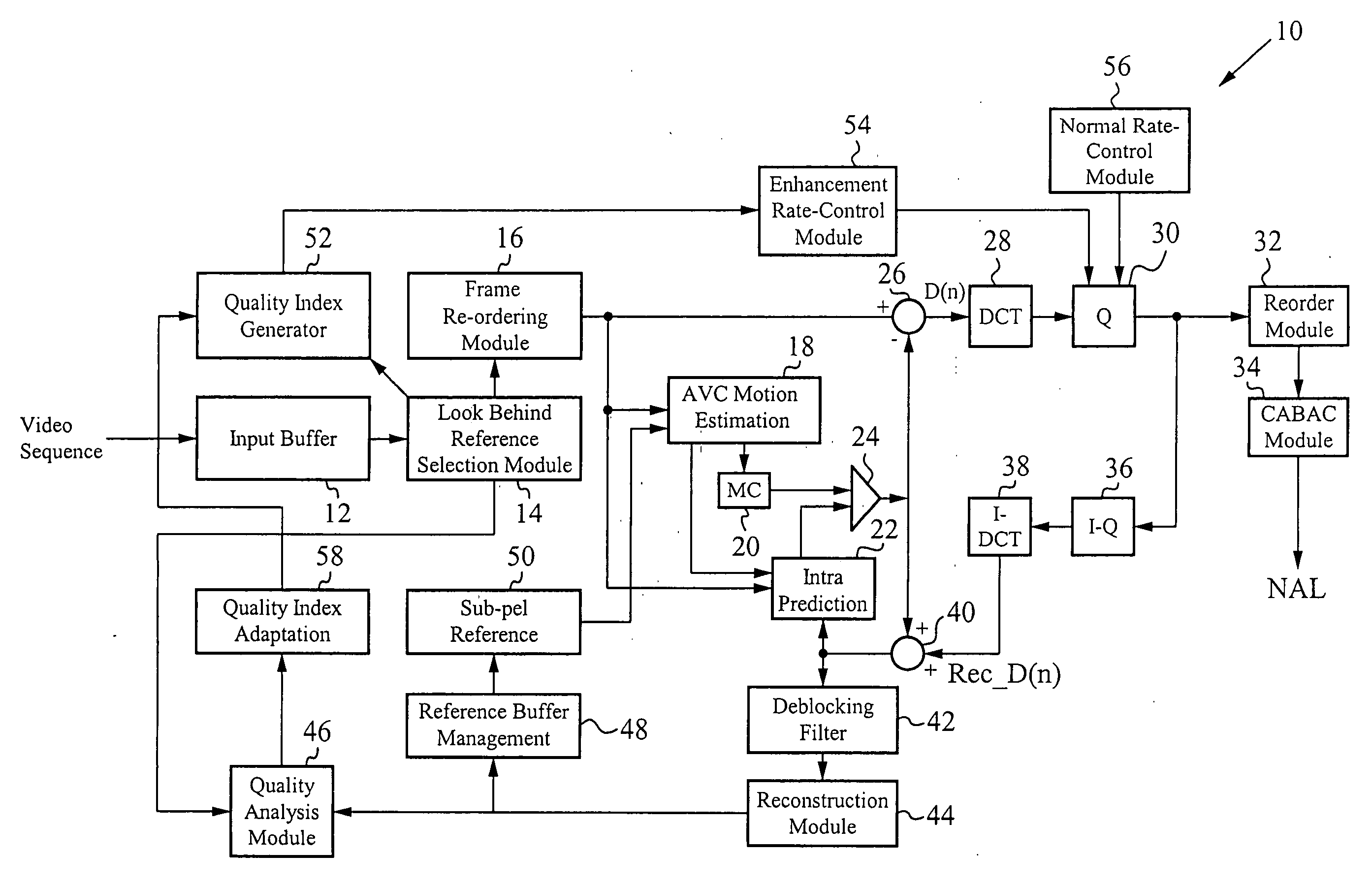
[0029] Embodiments of a video coding system are directed to a bit-rate control module to provide frame enhancement and a long term look-behind reference frame module to provide an improved predictive scheme. Intra frame enhancement benefits the visual quality for the macroblocks that find a good match in the I-frame. Separately, look-behind prediction is utilized to find accurate prediction for uncovered objects if the look-behind reference frame has high quality. The video coding system combines these two qualities, thereby providing a coding scheme for encoding a video sequence.

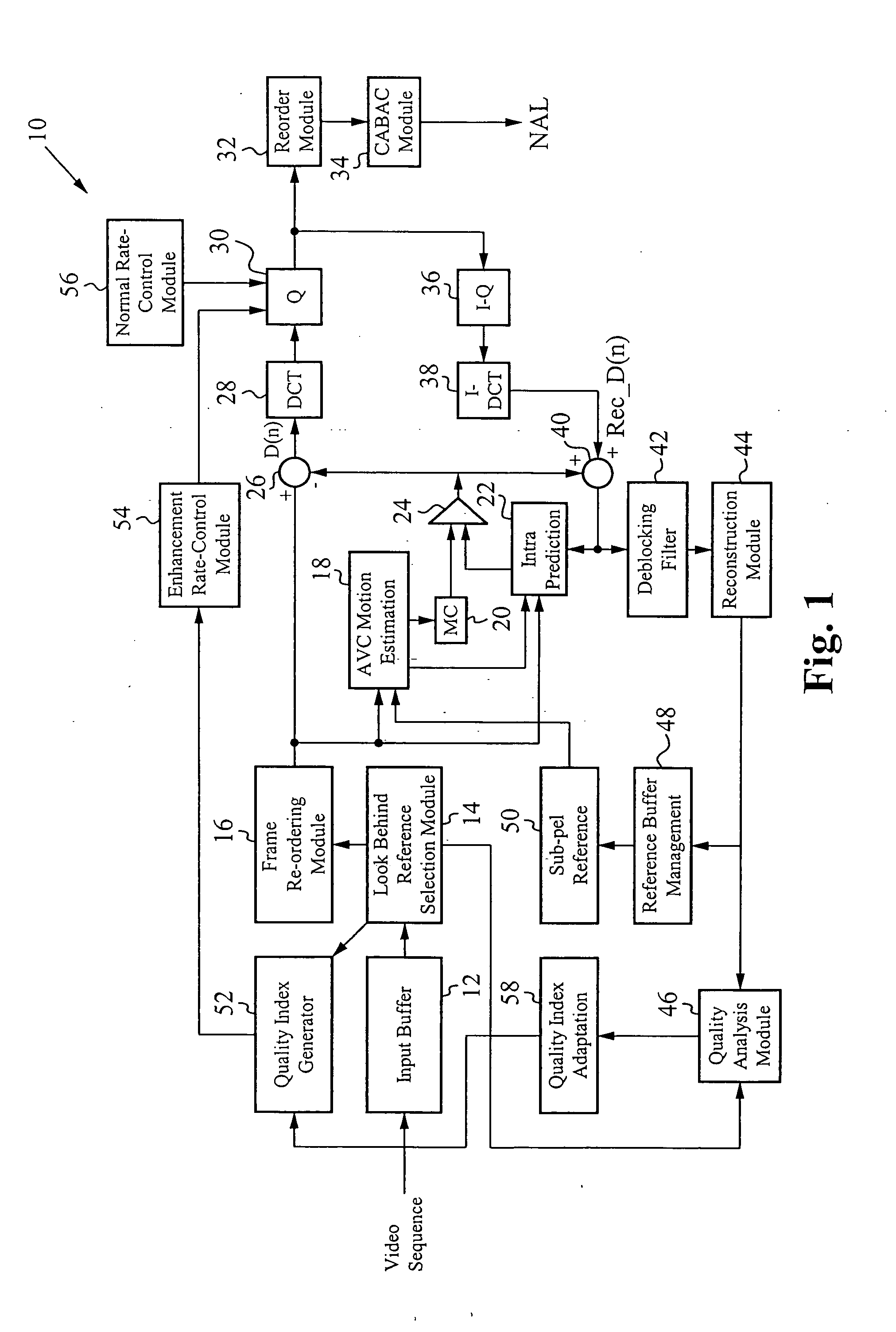
[0030]FIG. 1 illustrates an embodiment of an exemplary functional block diagram of a video coding system 10. A video sequence is first input into an input buffer 12. The video sequence includes a series of frames, or pictures. When the video sequence is formatted according to the MPEG standard, each frame is configured as either an I-frame, a P-frame, or a B-frame. Alternatively, the video sequence can be ...


PUM


Abstract

A video coding system receives as input a video sequence including a series of picture frames. One or more long term references are selected from the input video sequence, at least one of the long term references is a long term look-behind reference frame. Short term reference frames are also selected according to the standards. The frames are then re-ordered for encoding such that the long term look-behind reference is encoded first, followed by the remaining frames according to the conventional order dictated by the standards. Each frame is encoded according to motion estimation and motion compensation, and an intra prediction method that incorporates the use of the long term look-behind reference frame. Further, encoding of each long term look-behind reference frame includes quantization according to a controlled bit-rate. The bit-rate is increased for quantization of each long term look-behind reference frame, thereby increasing its quality. For each other frame, the bit rate is maintained at a normalized level.

Description

FIELD OF THE INVENTION [0001] The present invention relates to the field of video encoding. More particularly, the present invention relates to the field of high quality AVC encoding by using long term reference pictures enhancement and look behind reference pictures selection. BACKGROUND OF THE INVENTION [0002] A video sequence consists of a number of pictures, usually called frames. Subsequent frames are very similar, thus containing a lot of redundancy from one frame to the next. Before being efficiently transmitted over a channel or stored in memory, video data is compressed to conserve both bandwidth and memory. The goal is to remove the redundancy to gain better compression ratios. A first video compression approach is to subtract a reference frame from a given frame to generate a relative difference. A compressed frame contains less information than the reference frame. The relative difference can be encoded at a lower bit-rate with the same quality. The decoder reconstructs ...

Claims


Application Information

Patent Timeline
IPC IPC(8): H04N7/16
CPCH04N19/61H04N19/124H04N19/142H04N19/58H04N19/177H04N19/17H04N19/553H04N19/154
Inventor ZHANG, XIMINYAMAZAKI, TAKAO
Owner SONY CORP
Learn More