Apparatus for calculating quantity indicating charged state of on-vehicle battery

a technology of on-vehicle battery and apparatus, which is applied in the control arrangement of battery/fuel cell, instruments, electrochemical generators, etc., can solve the problems of increasing the parts cost of signal processing circuit, raising the parts cost, and lowering the s/n (signal to noise ratio) ratio, so as to reduce the errors of internal resistance (rd), the effect of simple calculation

Active Publication Date: 2007-08-30
DENSO CORP +1
View PDF0 Cites 46 Cited by
  • Summary
  • Abstract
  • Description
  • Claims
  • Application Information

AI Technical Summary

Benefits of technology

[0020] An inventors' study showed that the open voltage difference (ΔVo) can be related well, in a positive correlation, to amounts of change in the internal resistance (Rd) which are caused a pseudo circuit-open voltage of the battery given before starting up the starter and a further pseudo circuit-open voltage of the battery given after the cranking period. Thus, the correcting function (f(ΔVo)) showing both the open voltage difference (ΔVo) and the internal resistance Rd can be memorized in advance. Applying the value of an open voltage difference (ΔVo) to be calculated to this correcting function (f(ΔVo)) allows a changed value (ΔRd) of the internal resistance (Rd) to be corrected. T

Problems solved by technology

To have such a high signal processing performance results in a rise in parts costs of the signal processing circuit.
The current sensor should therefore have a very large dynamic range, which also becomes. a factor in raising the parts costs.
On the other hand, it is inevitable that the fast-operating current sensor and the analog/digital signal processor are influenced largely by high-frequency components of radio noise and thermal noise, thereby l

Method used


Image

  • Apparatus for calculating quantity indicating charged state of on-vehicle battery
  • Apparatus for calculating quantity indicating charged state of on-vehicle battery
  • Apparatus for calculating quantity indicating charged state of on-vehicle battery

Examples


first embodiment

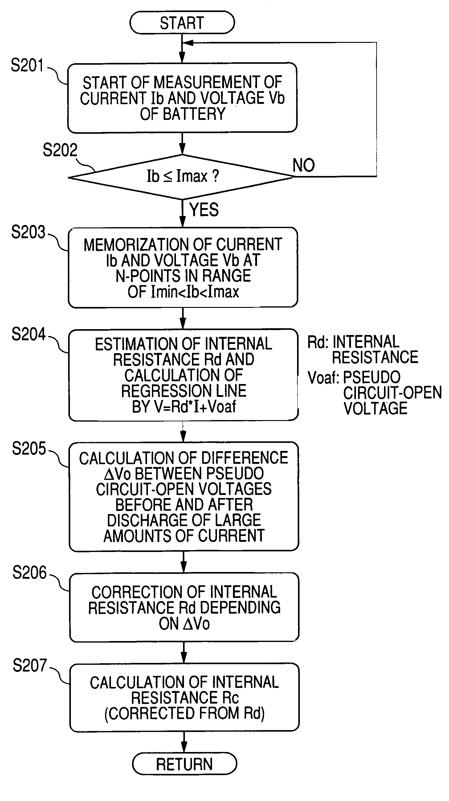
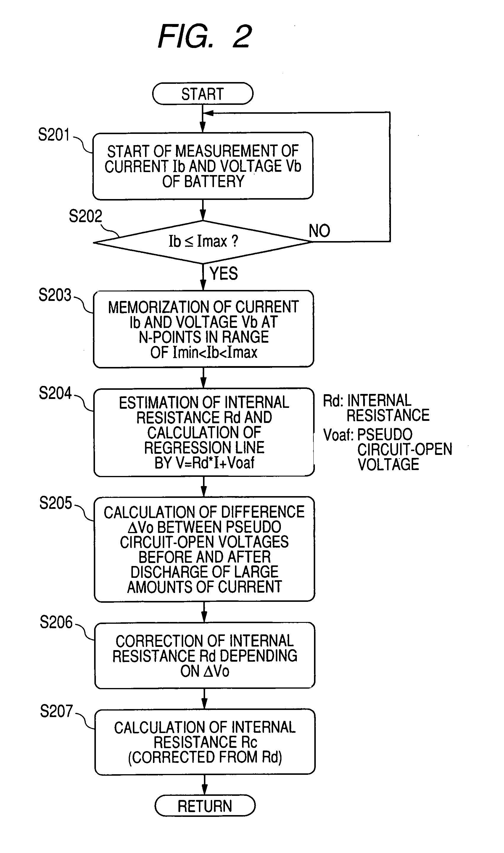
[0037] Referring to FIGS. 1-6, a first embodiment of the charged-state quantity calculating apparatus according to the present invention will now be described. In the present embodiment, the calculating apparatus is reduced into practice by being functionally incorporated in an on-vehicle power system 1.

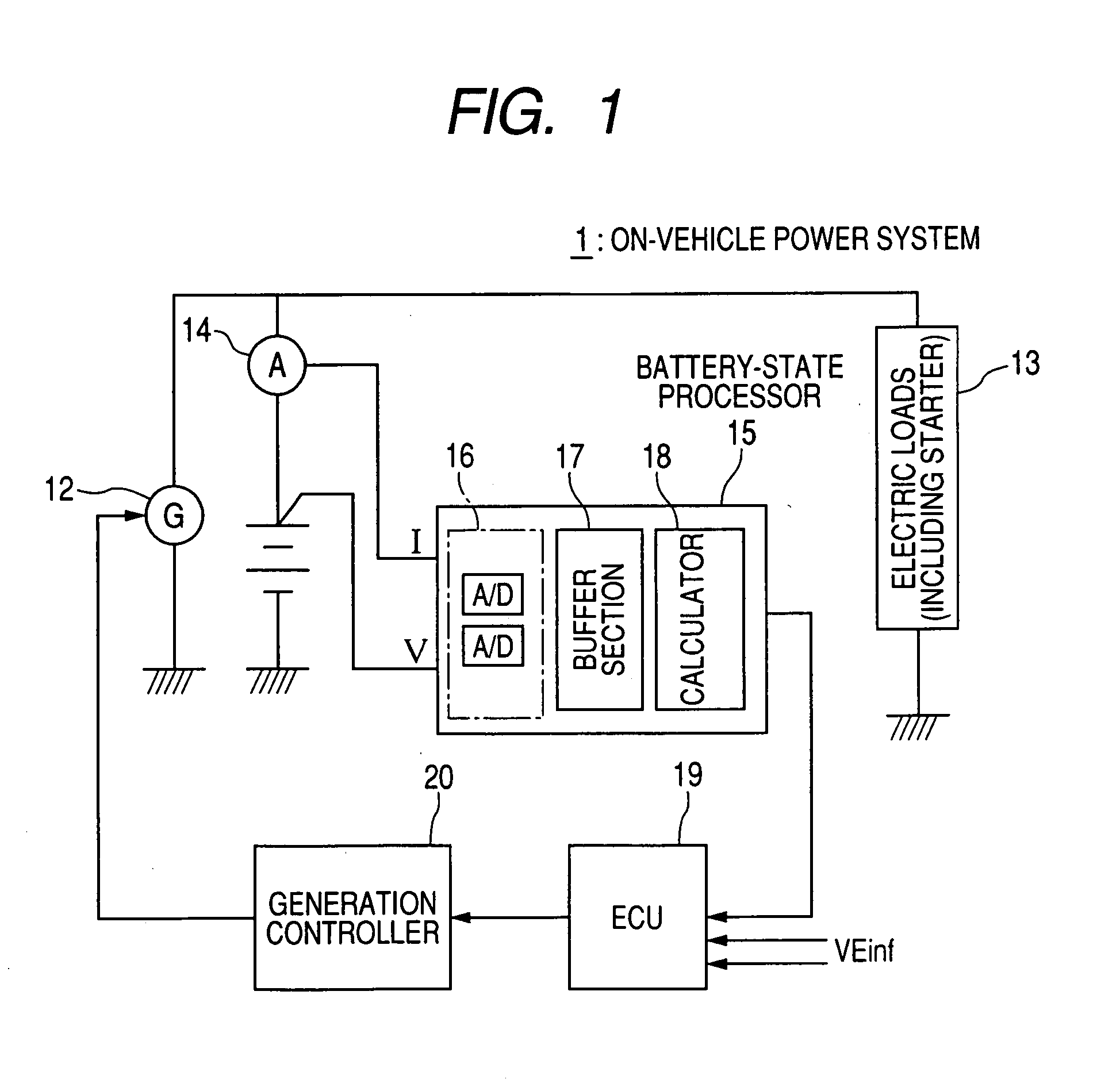
[0038]FIG. 1 shows a block diagram outlining the configuration of the on-vehicle power system 1.

[0039] The on-vehicle power system 1 shown in FIG. 1 includes a battery 11 which composes a power storing device to store electric power therein, an on-vehicle generator 12 driven by an on-vehicle engine (not shown), on-vehicle electric loads 13, a current sensor 14, and a battery-state processor 15. Of these, the battery 11 is a target of which internal state, that is, charged state is detected. This battery 11 is composed of a lead battery, a nickel metal-hydride battery, a lithium battery, or others. The on-vehicle electric loads 13 include a starter for starting up the engine.

[0040]...

second embodiment

[0065] Referring to FIGS. 7 and 8, a second embodiment of the charged-state quantity calculating apparatus according to the present invention will now be described. In the same way as the first embodiment, the calculating apparatus is reduced into practice by being functionally incorporated in an on-vehicle power system 1, which is the same in the configuration as that shown in FIG. 1.

[0066] The on-vehicle power system 1 according to the second embodiment is characteristic of using the internal resistance Rc on the formula (4) in order to estimate a lower limit voltage in starting up the engine (i.e., the starter). This estimation is very important in situations such as idle-stop running requiring frequent engine restarts (engine stop to engine restart in the idling) in order to secure that the battery 11 keeps a sufficient restart performance.

[0067] The present embodiment exemplifies estimating the lower limit voltage in the next startup the engine from the calculated internal re...

third embodiment

[0070] Referring to FIGS. 9-11, a third embodiment of the charged-state quantity calculating apparatus according to the present invention will now be described. In the same way as the foregoing embodiments, the calculating apparatus is reduced into practice by being functionally incorporated in an on-vehicle power system 1, which is the same in the configuration as that shown in FIG. 1.

[0071] The on-vehicle power system 1 according to the third embodiment further improves the performance to be obtained from the configuration in the second embodiment.

[0072] The second embodiment shows that, as described, using the internal resistance Rc allows the lower limit voltage to be estimated with higher precision. In contrast, the third embodiment improves a difficulty which may occur in a situation where the internal state (i.e., charged state) of the battery 11. changes in a period of time from the calculation of the internal resistance Rc to the next startup of the engine. In such a situ...


PUM


Abstract

An apparatus is provided to calculate a quantity indicating a charged state of an on-vehicle battery. The battery powers a starter starting up an on-vehicle engine. In the apparatus, a plurality of pairs of data consisting of current and voltage of the battery are acquired at predetermined sampling intervals during a cranking period of the engine in response to starting up the starter. At intervals, a value of an internal resistance of the battery is calculated based on the plurality of pairs of data of current and voltage. The internal resistance is one kind of the charged-state indicating quantity. An open voltage difference is calculated, which is a difference between a pseudo circuit-open voltage of the battery given before starting up the starter and a pseudo circuit-open voltage of the battery given after the cranking period. The value of the internal resistance is corrected using the open voltage difference.

Description

CROSS REFERENCE TO RELATED APPLICATION [0001] The present application relates to and incorporates by reference Japanese Patent application No. 2006-49038 filed on Feb. 24, 2006. BACKGROUND OF THE INVENTION [0002] 1. Field of the Invention [0003] The present invention relates to an apparatus for calculating a quantity indicating the charged state (also called “internal charged state” or “internal state”) of a secondary (rechargeable) battery mounted on a vehicle, and in particular, to the apparatus that calculates the charged state using at least a plurality of pairs of voltage and current acquired from the on-vehicle battery. [0004] 2. Description of the Related Art [0005] In general, it is required that the capacity and safety of on-vehicle battery systems be strictly managed. To perform such a management, the charged state of an on-vehicle battery system should be estimated with precision. [0006] Several apparatuses to provide some techniques for the estimation have now been propo...

Claims


Application Information

Patent Timeline
IPC IPC(8): G01N27/416B60L50/10
CPCG01R31/006G01R31/3662G01R31/3648G01R31/389Y02E60/10H01M10/48G01R31/374G01R31/367G01R31/3842G01R31/52G01R19/10G01R19/16528G01R19/12B60L58/12H02J7/0048
Inventor MIZUNO, SATORUTANAKA, KATSUNORI
Owner DENSO CORP
Why Eureka
Try Eureka