Reflection type liquid crystal display device and method of manufacturing the same

a liquid crystal display and reflection type technology, applied in the direction of organic semiconductor devices, non-linear optics, instruments, etc., can solve the problems of high power dissipation, large volume, heavy weight,

Inactive Publication Date: 2007-08-30
LEE JEONG HO +2
View PDF3 Cites 3 Cited by
  • Summary
  • Abstract
  • Description
  • Claims
  • Application Information

AI Technical Summary

Benefits of technology

[0029] The present invention has been made to solve the aforementioned problem, and accordingly, it is an object of the present invention to provide a reflection type liquid crystal display device in which a battery effect can be prevented when a pad electrode consisting of a transparent conductive layer is used.
[0030] It is another object of the present invention to provide a method of manufacturing a reflection type liquid crystal display device in which a battery effect can be prevented when a pad electrode consisting of a transparent conductive layer is used.
[0035] According to the present invention, the pad electrode comprised of the transparent conductive layer is formed after an opening region of the first passivation layer, i.e., the pad contact hole, is formed so as to be extended to a position under the second passivation layer located on the boundary region between the display region and the pad region. Thus, the second passivation layer covers a portion where step coverage of the pad electrode is poor due to a stepped portion of the opening region, i.e., an undercut of the second metal layer. Therefore, it can be prevented chemicals from penetrating through the stepped portion of the opening region to cause the battery effect between the pad electrode and the second metal layer of the wiring layer, thereby preventing a lifting of the pad electrode and a corrosion of the second metal layer.

Problems solved by technology

The CRT, however, has some disadvantages such as a heavy weight, a large volume and high power dissipation.
Thus, during a subsequent chip on glass (COG) bonding process by which integrated circuits are directly mounted on the substrate of the LCD panel, COG (chip on glass) block defects may be caused due to aluminum corrosion.

Method used


Image

  • Reflection type liquid crystal display device and method of manufacturing the same
  • Reflection type liquid crystal display device and method of manufacturing the same
  • Reflection type liquid crystal display device and method of manufacturing the same

Examples


Embodiment Construction

[0043] Hereinafter, a reflection type liquid crystal display device and a method of manufacturing the reflection type liquid crystal display device according to the preferred embodiments of the present invention will be described in detail with reference to the accompanying drawings.

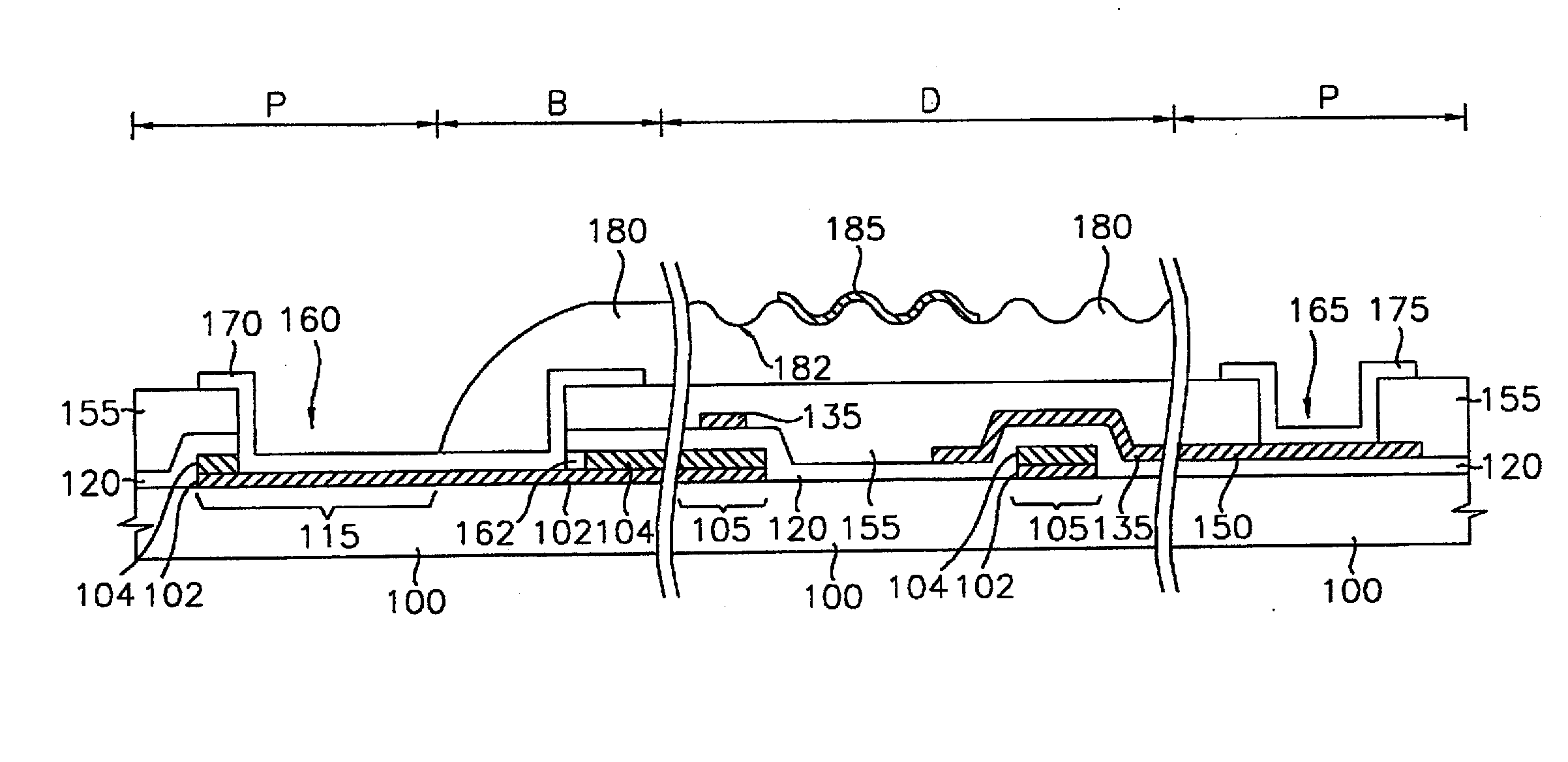
[0044]FIG. 3 is a plan view showing a reflection type liquid crystal display device according to the present invention. FIGS. 4A and 4B are cross-sectional views of the reflection type liquid crystal display device, taken along lines E-E′ and F-F′ in FIG. 3, respectively. The reflection type liquid crystal display device includes an amorphous silicon thin film transistor having a bottom-gate structure. Here, a reference symbol P shows a pad region; a reference symbol D indicated a display region; and a reference symbol B shows a boundary region located between the pad region and the display region. Here, the pad region P is formed outside the display region D so as to surround the display region D.

[004...


PUM

PropertyMeasurementUnit
thicknessaaaaaaaaaa
temperatureaaaaaaaaaa
transparentaaaaaaaaaa

Abstract

Disclosed are a reflection type LCD and method of manufacturing the same. A wiring layer having a first and second metal layer (102, 104) is formed on a substrate (100) including a display region (D) and a pad region (P). Upon the substrate (100) and the wiring layer is formed a first passivation layer (155), and contacts with a wiring terminal (115) and the first metal layer (102). A second passivation layer (180) is formed on the substrate except the pad region (P). The pad contact hole (160) extends to a position under the second passivation layer (180). The second passivation layer (180) covers a region in the pad contact hold (160) where the step coverage of the pad electrode (170) is poor, thereby preventing a battery effect.

Description

TECHNICAL FIELD [0001] The present invention relates to a liquid crystal display device and a method of manufacturing the same, and more particularly to a reflection type liquid crystal display device and a method of manufacturing the same in which a battery effect can be prevented when a pad electrode consisting of a transparent conductive layer is used. BACKGROUND ART [0002] In the information society of these days, electronic display devices are more important as information transmission media and various electronic display devices are widely applied for industrial apparatus or home appliances. Such electronic display devices are being continuously improved to have new appropriate functions for various demands of the information society. [0003] In general, electronic display devices display and transmit various pieces of information to users who utilize such information. That is, the electronic display devices convert electric information signals outputted from electronic apparat...

Claims


Application Information

Patent Timeline
Patent Type & Authority Applications(United States)
IPC IPC(8): G02F1/1335H05B33/04H01L51/50H01L51/52H05B33/10H05B33/12H05B33/14
CPCH01L2251/5315H01L51/5237H10K2102/3026H10K59/874H10K59/872H05B33/04H10K50/846H10K50/841
Inventor LEE, JEONG-HOCHOI, SANG-GUNSONG, YOUNG-GOO
Owner LEE JEONG HO
Why Eureka
Try Eureka