
Methods and systems for performing angle-resolved fourier-domain optical coherence tomography

a fourier-domain optical coherence and tomography technology, applied in the field of methods and systems for performing angle-resolved fourier-domain optical coherence tomography, can solve the problems of system generally not scaling appropriately to a large number of angles, difficult to discern subtle reflectance differences in tissue reflectance, and only one angular range centered at 180 degrees is collected. to achieve the effect of facilitating the production of data associated

Active Publication Date: 2007-08-30
THE GENERAL HOSPITAL CORP
View PDF99 Cites 52 Cited by
  • Summary
  • Abstract
  • Description
  • Claims
  • Application Information

AI Technical Summary

Benefits of technology

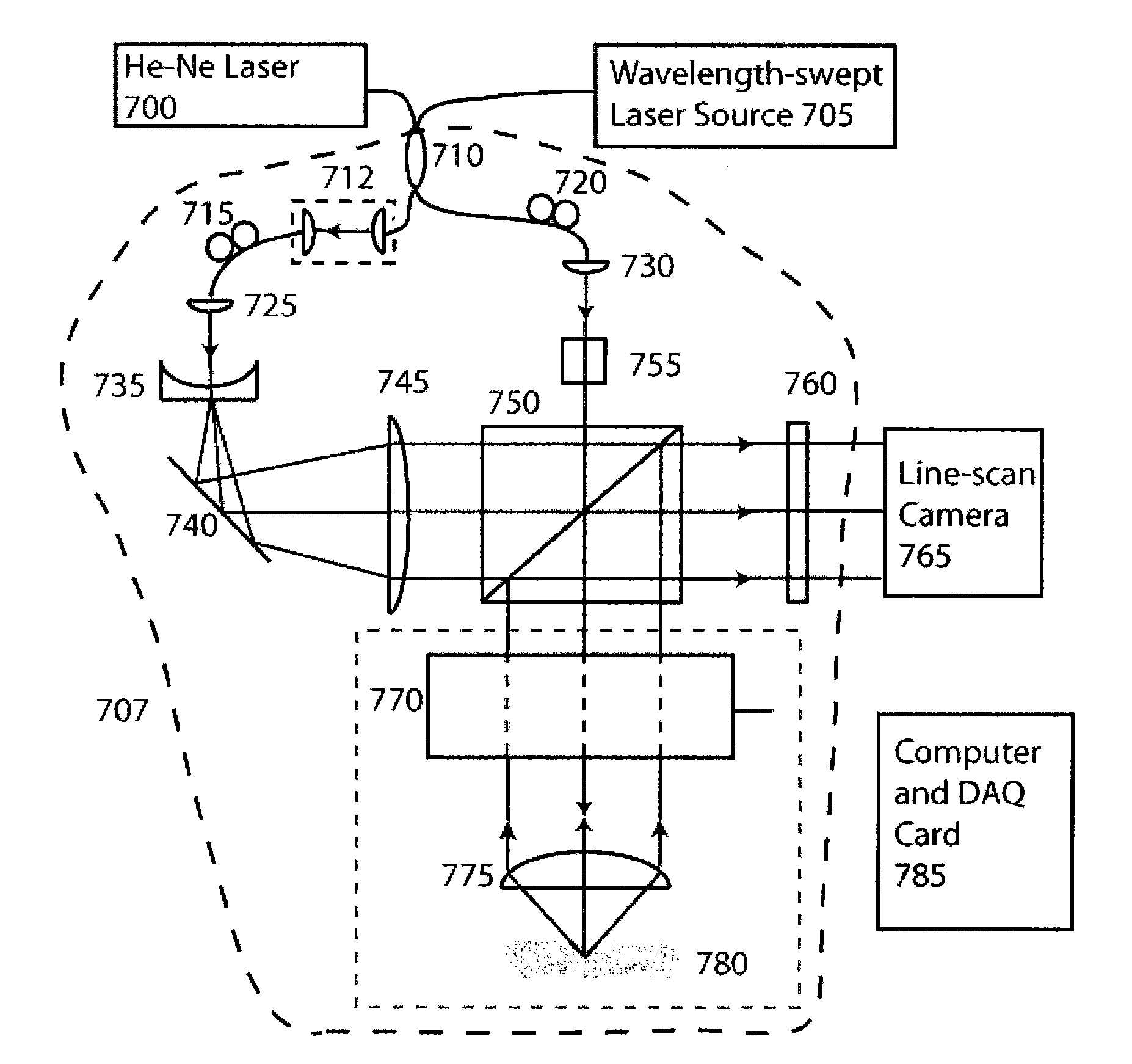
[0015]According to another exemplary embodiment of the present invention, apparatus and method can provided which facilitate the production of data associated with at least one sample. For example, first information associated with signals for a plurality of electro-magnetic radiations provided from the at least one sample can be received. At least first one of the electro-magnetic radiations may be provided along a first axis, and at least second one of the electro-magnetic radiations can be provided along second axis which is different from the first axis. Data for each of the signals within at least one portion of the first information may include data for a plurality of depths within the sample. Second information associated with contrast data of at least one portion of an image for the at least one sample can be produced as a function of the first information.

Problems solved by technology

One limitation of conventional OCT systems and methods is that the backscattered light from only one angular range centered at 180 degrees is collected.
Speckle generally manifests itself as a checkered pattern within scattering regions of the image, and makes it more difficult to discern subtle reflectance differences in the tissue reflectance.
While being amenable to high-speed imaging, these method and system generally do not scale appropriately to a large number of angles, and can involve a tradeoff between the spatial resolution and the number of angles acquired thereby.
Such method and system likely do not provide for (or even allow) a measurement of angular backscattering distributions.
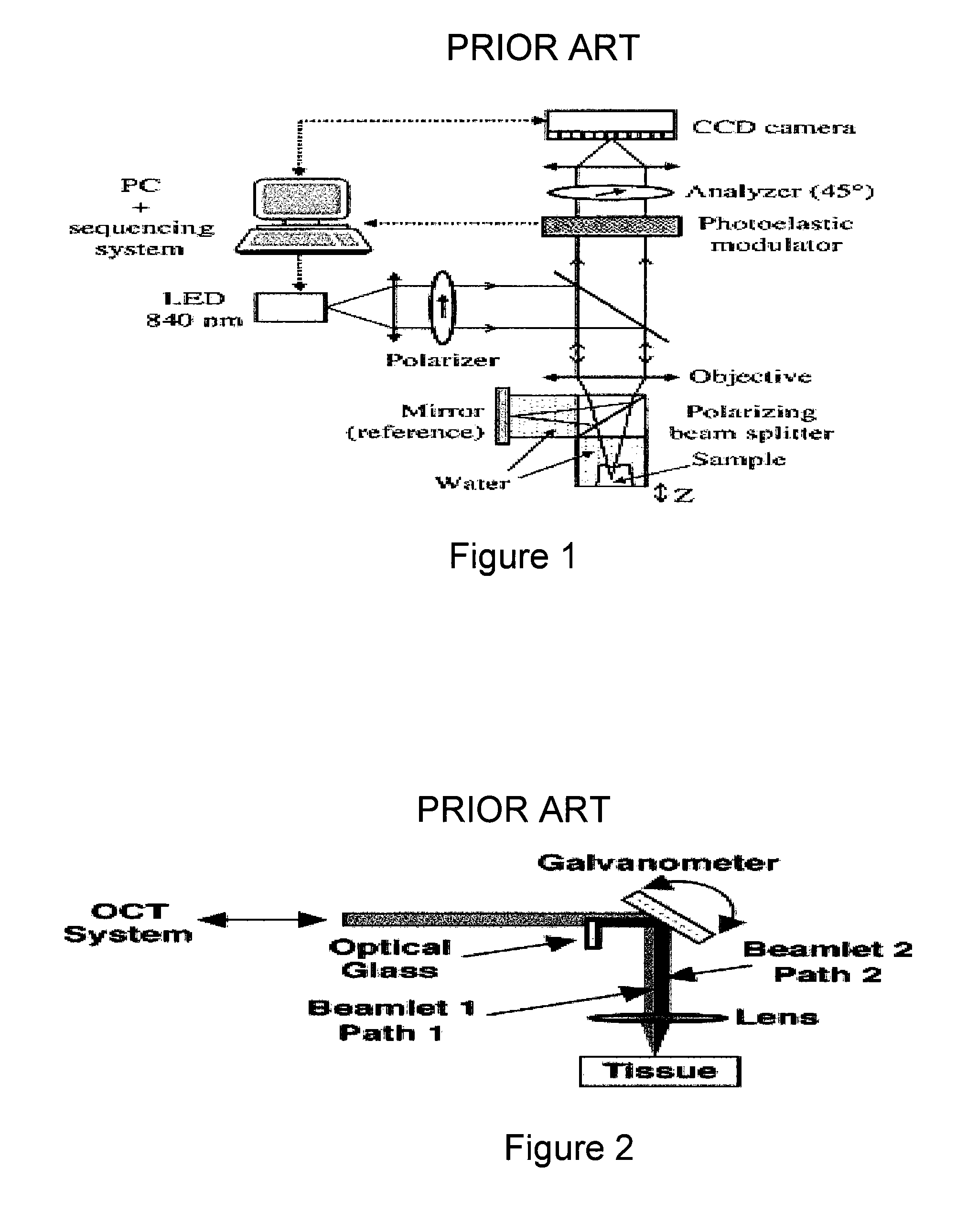
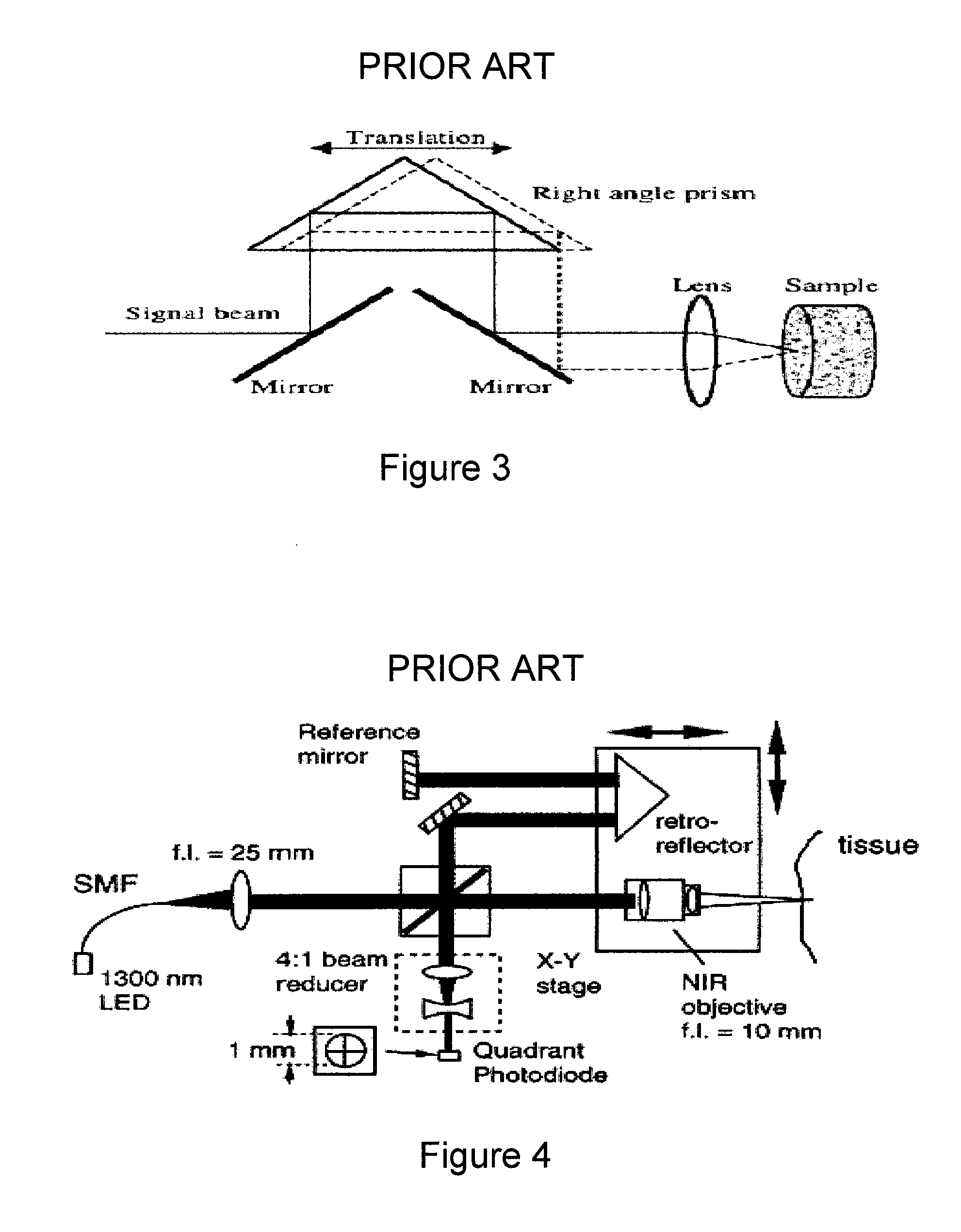
The speed at which the images can be acquired may be limited by the speed at which the prism can be translated in an oscillatory manner.
Thus, this system may not be conducive to measurements of the angular backscattering distributions.
These techniques generally do not permit simultaneous measurements of the angular backscattering distributions, and the measurement speed is likely limited by the speed at which the lens can be precisely translated.
While optimized for angular, point-sampling, in-situ measurements, angle-resolved LCI in its current implementations may likely be unsuitable for in-vivo clinical imaging.

Method used


Image

  • Methods and systems for performing angle-resolved fourier-domain optical coherence tomography
  • Methods and systems for performing angle-resolved fourier-domain optical coherence tomography
  • Methods and systems for performing angle-resolved fourier-domain optical coherence tomography

Examples


example

[0072]The exemplary embodiment of the system and method according to the present invention which can be used for reducing speckle was verified by the following experiment. Two-layer tissue phantoms were constructed from aqueous agar gel (0.5% agar by weight) and polymer microspheres of diameter 0.3 mm (Duke Scientific). The phantoms were contained in silicone isolators (Sigma). An initial scattering layer with an approximate depth of 2 mm was formed. A second scattering layer, designed to have a lower scattering coefficient than the first, was formed on top of the first and had an approximate depth of 450 mm. By analyzing the exponential signal attenuation with respect to depth, the total scattering coefficients were estimated to be 24 cm-1 and 12 cm-1 for the first and second layers, respectively.

[0073]The two-dimensional image generated from a single angular sample shows significant speckle, as shown in FIG. 11(a), in which the boundary between the two layers is not clearly visibl...


PUM


Abstract

Arrangements, apparatus and methods are provided according to exemplary embodiments of the present invention. In particular, at least one first electro-magnetic radiation may be received and at least one second electro-magnetic radiation within a solid angle may be forwarded to a sample. The second electro-magnetic radiation may be associated with the first electro-magnetic radiation. A plurality of third electro-magnetic radiations can be received from the sample which is associated with the second electro-magnetic radiation, and at least one portion of the third electro-magnetic radiation is provided outside a periphery of the solid angle. Signals associated with each of the third electro-magnetic radiations can be simultaneously detected, with the signals being associated with information for the sample at a plurality of depths thereof. The depths can be determined using at least one of the third electro-magnetic radiations without a need to utilize another one of the third electro-magnetic radiations.

Description

CROSS-REFERENCE TO RELATED APPLICATION(S)[0001]This application is based upon and claims the benefit of priority from U.S. Patent Application Ser. No. 60 / 776,544, filed Feb. 24, 2006, the entire disclosure of which is incorporated herein by reference.STATEMENT REGARDING FEDERALLY SPONSORED RESEARCH[0002]The invention was made with the U.S. Government support under Contract No. R01 CA103769 awarded by the National Institutes of Health. Thus, the U.S. Government has certain rights in the invention.FIELD OF THE INVENTION[0003]The present invention relates to methods and systems for performing angle-resolved Fourier-domain optical coherence tomography, and more particularly to measuring spatially-resolved angular backscattering distributions from transparent and turbid samples using Fourier-domain optical coherence tomography techniques.BACKGROUND OF THE INVENTION[0004]Optical coherence tomography (“OCT”) enables cross-sectional images of biological samples to be obtained with resolutio...

Claims


Application Information

Patent Timeline
IPC IPC(8): G01B11/02
CPCA61B5/0073G01N21/4795G01N2021/4714G01B9/02087G01B9/02043G01B2290/70G01B9/02091A61B5/0066
Inventor DESJARDINS, ADRIEN E.VAKOC, BENJAMIN J.TEARNEY, GUILLERMO J.BOUMA, BRETT EUGENE
Owner THE GENERAL HOSPITAL CORP
Learn More