Surge protection device disconnector

a technology of protection device and disconnector, which is applied in the direction of overvoltage protection resistor, emergency protection arrangement for limiting excess voltage/current, and arrangement responsive to excess voltage, etc., can solve the problems of movable, short-circuiting of electrical conductor, and dramatic drop of the impedance of the element,

Inactive Publication Date: 2007-08-30
EATON CORP
View PDF4 Cites 22 Cited by
  • Summary
  • Abstract
  • Description
  • Claims
  • Application Information

AI Technical Summary

Benefits of technology

[0019] According a first aspect of the present invention, a surge protection device is provided for protecting a load that is connected to at least one voltage source from a power grid. The device includes an overcurrent fuse electrically connected to the at least one voltage source, a thermal fuse spring electrically connected to the overcurrent fuse, a fuse trace electrically connected to the thermal fuse spring, and a transient suppressing element, such as an MOV or SAD, electrically connected to the fuse trace. In addition, the overcurrent fuse, the thermal fuse spring, and the transient suppressing element are electrically connected in series between the at least one voltage source and a neutral or ground connection. This configuration provides protection over the full range of fault currents because the overcurrent fuse, the thermal fuse spring, and the fuse trace have overlapping ranges and one or more of them will open in response to low, medium and high fault currents. In the preferred embodiment, the overcurrent fuse is encapsulated in a non-organic material such as silicone. As shown in FIG. 2, the device may include a plurality of thermal fuse springs electrically connected to the overcurrent fuse a plurality of parallel fuse trace combinations and a plurality of transient suppressing elements.
[0021] A further aspect of the invention relates to a surge protection device that includes a substrate having a slot provided therein, a transient suppressing element, such as an MOV or SAD, provided on the substrate, and a thermal fuse spring provided on the substrate. The thermal fuse spring has a finger having a first end and a second end that is biased toward the first end. The first end of the finger is attached to the substrate, such as through a base forming part of the thermal fuse spring, on a first side of the slot and the second end of the finger is attached to the substrate on a second side of the slot opposite the first side. The second end, when attached to the substrate, is electrically connected to the transient suppressing element. The second end of the finger is preferably attached to the substrate and electrically connected to the first end of the fuse trace by a solder material, wherein when the solder material is caused to melt, the second end of the finger moves toward the first end of the finger over the slot. The slot serves to reduce the likelihood that an arc is generated as the second end of the finger moves toward the first end of the finger, thereby opening the fuse. A fuse trace may be provided on the substrate between the second end of the finger and the transient suppressing element. In one embodiment, the device includes a plurality of transient suppressing elements and a plurality of thermal fuse springs provided on the substrate

Problems solved by technology

Electrical systems, such as electrical power distribution systems, periodically experience over-voltage conditions, such as transient over-voltage conditions, also called “surges.” Over-voltage conditions are problematic to electrical systems because they may cause damage to the loads, such as electronic devices or other hardware, that are coupled thereto.
When the voltage across a transient-suppressing element exceeds a predetermined threshold rating, however, the impedance of the element drops dramatically, essentially short-circuiting the electrical conductors and “shunting” the current associated with the over-voltage through the transient-suppressing element and away from the load.
MOVs, however, have operational limitations that must be taken into account when designing an SPD.
Specifically, all MOVs have a maximum surge current rating that, if exceeded, may cause the MOV to fail.
An MOV may also fail if subjected to repeated operation, even if the maximum transient current rating is never exceeded.
This current, if not interrupted, will drive the MOV into a thermal runaway condition, typically resulting in an explosive failure of the MOV (involving, for example, fire, toxic smoke and / or hot particles) and damage to or destruction of the SPD and surrounding components.
The problem with such enclosures is that, despite the heavy metal walls, the enclosures have been known to rupture, release toxic gas and / or not prevent fire in all instances.
The problem with prior art designs that use fuses to protect against MOV failure is that fuses, while effective in certain particular ranges, are not reliable over the full range of fault currents that may occur.
If fuse traces would be designed to handle relatively high surge and fault currents it they would not be suitable for disconnecting a failing MOV under relatively lower fault current conditions.
Another problem encountered by prior art SPD designs is due to the fact that it is possible, particularly under TOV conditions, to generate excessive heat in an MOV without causing a series over-current fuse to open.
This excessive heat could cause damage to other components that could lead to a chain reaction of failures.
In addition, upon a failure of an MOV or its associated series fuse due to an overload condition, the MOV or fuse may disintegrate, causing electrically conductive debris to be dispersed in the vicinity of the MOV or fuse.
Thus, the main technical problem in SPD disconnector design is how to control arcing between metal parts inside the SPD because the arcing in combination with the debris may cause short-circuits in any electronic circuitry in the vicinity of the MOV or fuse, including other SPD circuits.
Epoxy, however, is very hard and therefore creates hazardous conditions under very high fault currents.
Specifically, under very high fault currents, the epoxy may explode catapulting many small bullet like projectile in the general vicinity of the SPD.
While effective, the SPD designs described in U.S. Pat. No. 6,636,409 are faced with many of the problems of prior art SPD designs described herein.
For example, the designs, while effective for certain low and high fault current ranges, is generally not effective for medium fault currents.
Thus, the designs may not be reliable over the full range of fault currents that may occur.
In addition, the designs may not effectively provide arc quenching in the case of an MOV failure.

Method used


Image

  • Surge protection device disconnector
  • Surge protection device disconnector
  • Surge protection device disconnector

Examples


Embodiment Construction

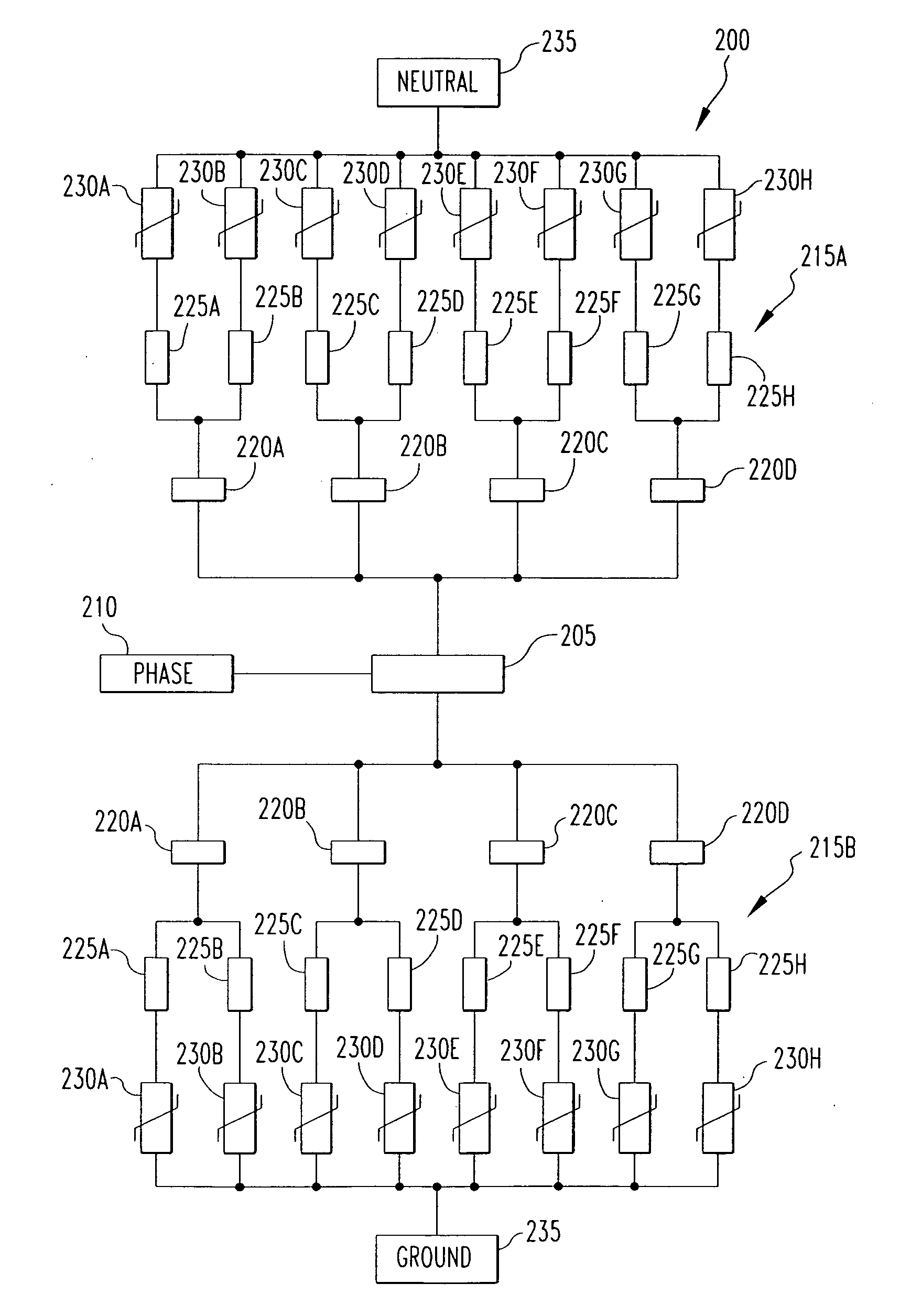
[0040]FIG. 2 is a schematic diagram of a surge protection device disconnector (SPDD) 200 according to an aspect of the present invention. SPDD 200 includes an overcurrent fuse 205 that is electrically connected to a phase conductor 210 of the electrical distribution system.

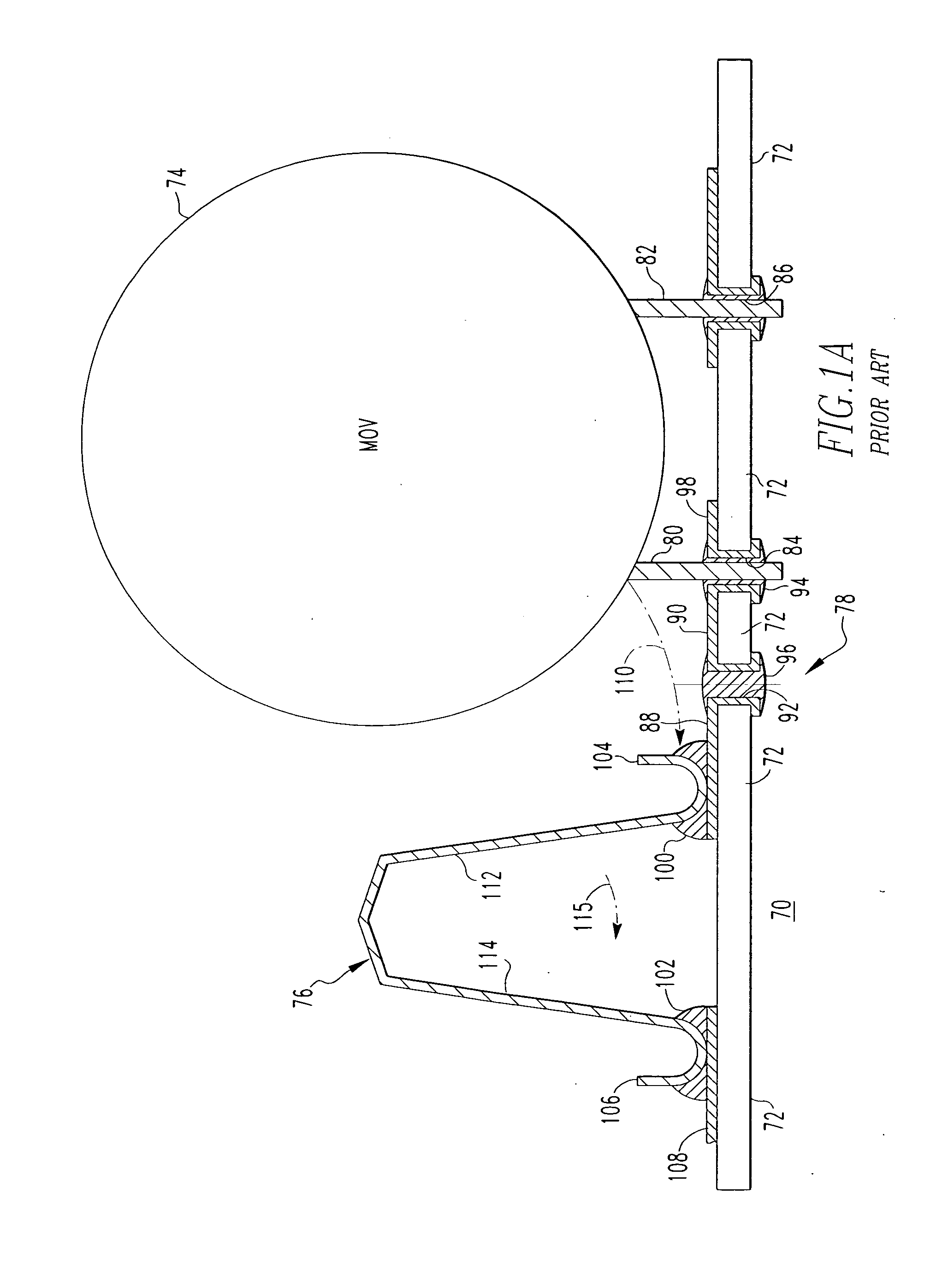
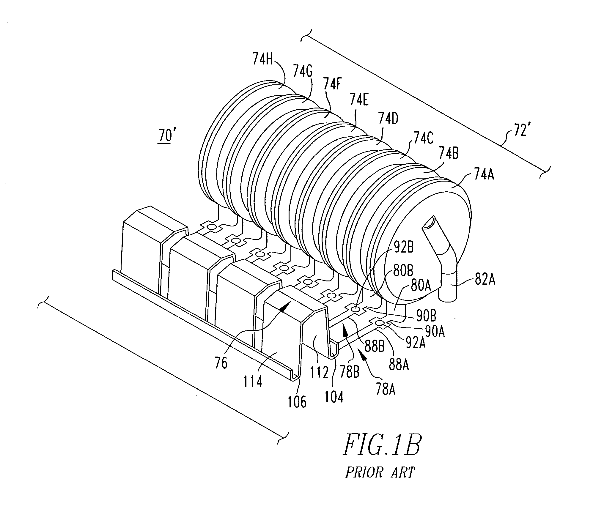
[0041] The SPDD 200 includes a first branch 215A and a second branch 215B which are identical to one another. Preferably, the first and second branches 215A and 215B are each similar in structure to the SPD′70 shown in FIG. 1B and described above or the SPD shown in FIG. 1D. For clarity, only the first branch 215A will be described, but it will be understood that the second branch 215B includes identical components. The first branch 215A includes thermal fuse springs (TFS) 220A, 220B, 220C and 220D in the form shown in either FIG. 1A or FIGS. 1C and 1D which are each electrically connected to the overcurrent fuse 205 as seen in FIG. 2. The thermal fuse springs (TFS) 220A, 220B, 220C and 220D are preferably part o...


PUM


Abstract

A number of surge protection device disconnector designs provide protection to a load over a full range of fault currents provide adequate surge protection as well. The designs quench arcs that may tend to occur as a result of MOV faults, thereby protecting the surrounding components.

Description

FIELD OF THE INVENTION [0001] The present invention relates to surge protection devices, and in particular to a number of surge protection device disconnector designs. BACKGROUND OF THE INVENTION [0002] Electrical systems, such as electrical power distribution systems, periodically experience over-voltage conditions, such as transient over-voltage conditions, also called “surges.” Over-voltage conditions are problematic to electrical systems because they may cause damage to the loads, such as electronic devices or other hardware, that are coupled thereto. As a result, surge protection devices (SPDs) have been developed to protect the loads from over-voltages that would otherwise damage the loads. SPDs typically provide such protection by coupling various types of known transient-suppressing elements between the phase, and neutral and / or ground conductors of an electrical power distribution system. [0003] As is known in the art, transient-suppressing elements, such as metal-oxide var...

Claims


Application Information

Patent Timeline
Patent Type & Authority Applications(United States)
IPC IPC(8): H02H9/06
CPCH01C7/126H02H9/042H01H85/046H01H85/12H01H85/38H01H85/44H01H85/463H01H85/54H01H2037/046H01H2037/763H01H2085/0275H01H2085/0412H01H2085/0486H01H2085/385H01H37/761
Inventor KLADAR, DALIBORBANDURA, MIECZYSLAWDABROWSKI, HENRYK J.FUNKE, JAMESMARTZLOFF, FRANCOIS D.TOWLER, JOHN D.MENDOZA, ANTHONY C.HARTMAN, THOMAS C.
Owner EATON CORP
Why Eureka
Try Eureka