Acoustic signal generating apparatus

Inactive Publication Date: 2007-08-30
FUJITSU GENERAL LTD
View PDF5 Cites 4 Cited by
  • Summary
  • Abstract
  • Description
  • Claims
  • Application Information

AI Technical Summary

Benefits of technology

[0010]It is therefore an object of the invention to provide an acoustic signal generating apparatus that can eliminate occurrence of shock noise caused by fluctuation of the DC level of a low-pass filter before or after the signal output time period from PWM signal generator.

Problems solved by technology

In such a pulse width modulation amplification circuit, a pulse which becomes a carrier signal is output from the pulse width modulation circuit even in a state in which no audio signal is output and thus when power is turned on / off, shock noise caused by appearance / disappearance of the pulse occurs; this is a problem.
In the pulse width modulation amplification circuit in the related art described above, however, the analog circuits of the conversion means and the time constant circuit need to be provided separately and to cope with the problem, digital signal processing is insufficient; this is a problem.
If an audio signal is input, when the phase of the output of the exclusive-OR circuit is in a transition state, distortion occurs in the audio signal output to the load and thus muting must be applied for a given time period in the transition state; this is a problem.
An acoustic signal generating apparatus including oscillation means for generating a carrier signal of a predetermined frequency, PWM signal generator for pulse width modulating the carrier signal based on acoustic data, and a low-pass filter for converting a PWM signal output from the PWM signal generator into an analog acoustic signal without the above-described balanced transformerless amplification circuit cannot adopt the countermeasure based on phase adjustment described above; this is a problem.
If a signal is output from the PWM signal generator in synchronization before and after the pulse width modulating timing based on acoustic data and is fixed high or low in other time periods, the DC level of the low-pass filter fluctuates to the center level before and after the signal output time period and when the signal makes a center to high or low transition, shock noise occurs; this is also a problem.

Method used


Image

  • Acoustic signal generating apparatus
  • Acoustic signal generating apparatus
  • Acoustic signal generating apparatus

Examples


first embodiment

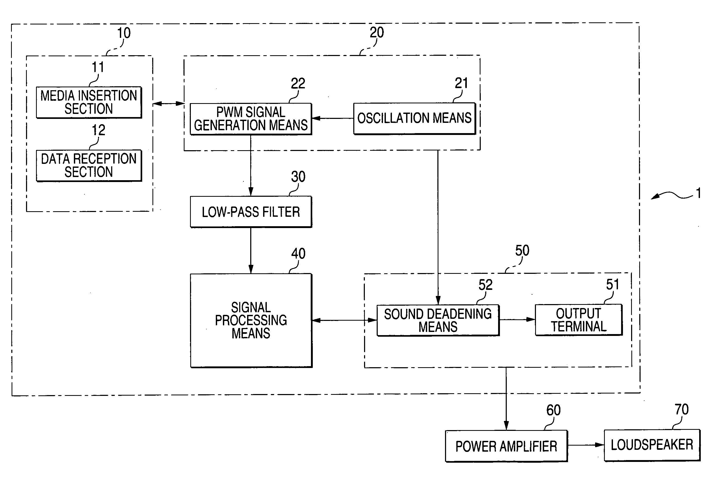
[0082]A first embodiment is an embodiment wherein the PWM signal generator 22 changes the duty ratio of the carrier signal in stages at a frequency outside the auditory area in a section AB just before a transition is made from an audio non-playback section A to an audio playback section B in FIG. 2B or a section BA just after a transition is made from the audio playback section B to the audio non-playback section A.

[0083]More particularly, in the case where the PWM signal generator 22 executes pulse width modulation based on acoustic data when audio playback is started, if the PWM signal is changed from low level LL to a pulse wave of duty ratio 1 / 2 at timing TA1 as shown in FIG. 3A, shock noise NA occurs in the process in which the output analog acoustic signal changes from low level LL to center level CL as shown in FIG. 3B.

[0084]In the first embodiment, however, the duty ratio of the PWM signal is changed in stages from timing TA2 preceding the timing TA1 as shown in FIG. 3C, wh...

second embodiment

[0088]A second embodiment is an embodiment wherein the PWM signal generator 22 smoothly changes the duty ratio of the carrier signal in accordance with the sine wave characteristic at a frequency outside the auditory area in the section AB or the section BA in FIG. 2B.

[0089]More particularly, when audio playback is started, in the cases in FIG. 3A and FIG. 3B, shock noise NA occurs in the process in which the output analog acoustic signal changes from low level LL to center level CL. In the second embodiment, however, the duty ratio of the PWM signal is smoothly changed in accordance with the sine wave characteristic from timing TA3 preceding the timing TA1 as shown in FIG. 4A whereby the output analog acoustic signal changes gently from low level LL to center level CL as shown in FIG. 4B. That is, the frequency of the analog acoustic signal becomes low at the gently changing timing; in the embodiment, the change percentage of the duty ratio of the PWM signal is lessened, whereby th...

third embodiment

[0092]A third embodiment is an embodiment wherein the PWM signal generator 22 always outputs a carrier signal whose duty ratio is 1 / 2 regardless of the state in the section A or the section B in FIG. 2B.

[0093]More particularly, when audio playback is started, in the cases in FIG. 3A and FIG. 3B, shock noise NA occurs in the process in which the output analog acoustic signal changes from low level LL to center level CL. In the third embodiment, however, the oscillation means 21 always outputs a carrier signal whose duty ratio is 1 / 2 regardless of the timing, namely, setting a state in which no low level LL exists in the carrier signal as shown in FIG. 5A, whereby the output analog acoustic signal is always maintained at center level CL as indicated by the solid line in FIG. 5B. That is, there is no difference between the low level LL and the center level CL in the audio non-playback state and the audio playback state as indicted by the dotted line in FIG. 5B and therefore the shock n...


PUM


Abstract

A PWM signal generator is operable to generate a first pulse signal and a second pulse signal at least one of before and after generating the first pulse signal. A duty ratio of the second pulse signal is gradually changed. A low-pass filter is operable to convert the first pulse signal output from the PWM signal generator into an analog acoustic signal. The low-pass filter is operable to convert the second pulse signal output from the PWM signal generator into the analog acoustic signal having an inaudible frequency.

Description

[0001]The disclosure of Japanese Patent Application No. 2006-053213 filed Feb. 28, 2006 including specification, drawings and claims is incorporated herein by reference in its entirety.BACKGROUND OF THE INVENTION[0002]This invention relates to an acoustic signal generating apparatus adopting a PWM (Pulse Wide Modulation) system converting the voltage amplitude of an acoustic signal into a digital pulse width based on digital acoustic data.[0003]Hitherto, there is provided a pulse width modulation circuit for pulse width modulating a supplied carrier signal based on the level of an audio signal and a pulse width modulation amplification circuit for outputting an output pulse of the pulse width modulation circuit and an inversion pulse to a balanced transformerless amplification circuit including a low-pass filter for driving a loudspeaker.[0004]In such a pulse width modulation amplification circuit, a pulse which becomes a carrier signal is output from the pulse width modulation circ...

Claims


Application Information

Patent Timeline
IPC IPC(8): H04R3/00H03F3/38H03F3/217
CPCH03F3/217H03F1/26
InventorYANAI, HIROYUKI
OwnerFUJITSU GENERAL LTD