
Car power source apparatus

Inactive Publication Date: 2007-08-30
SANYO ELECTRIC CO LTD
View PDF3 Cites 36 Cited by
  • Summary
  • Abstract
  • Description
  • Claims
  • Application Information

AI Technical Summary

Benefits of technology

[0010]The present invention was developed with the object of further resolving this drawback. Thus, it is a primary object of the present invention to provide a power source apparatus that can distribute airflow, in the direction of the air duct, uniformly to the battery compartment.
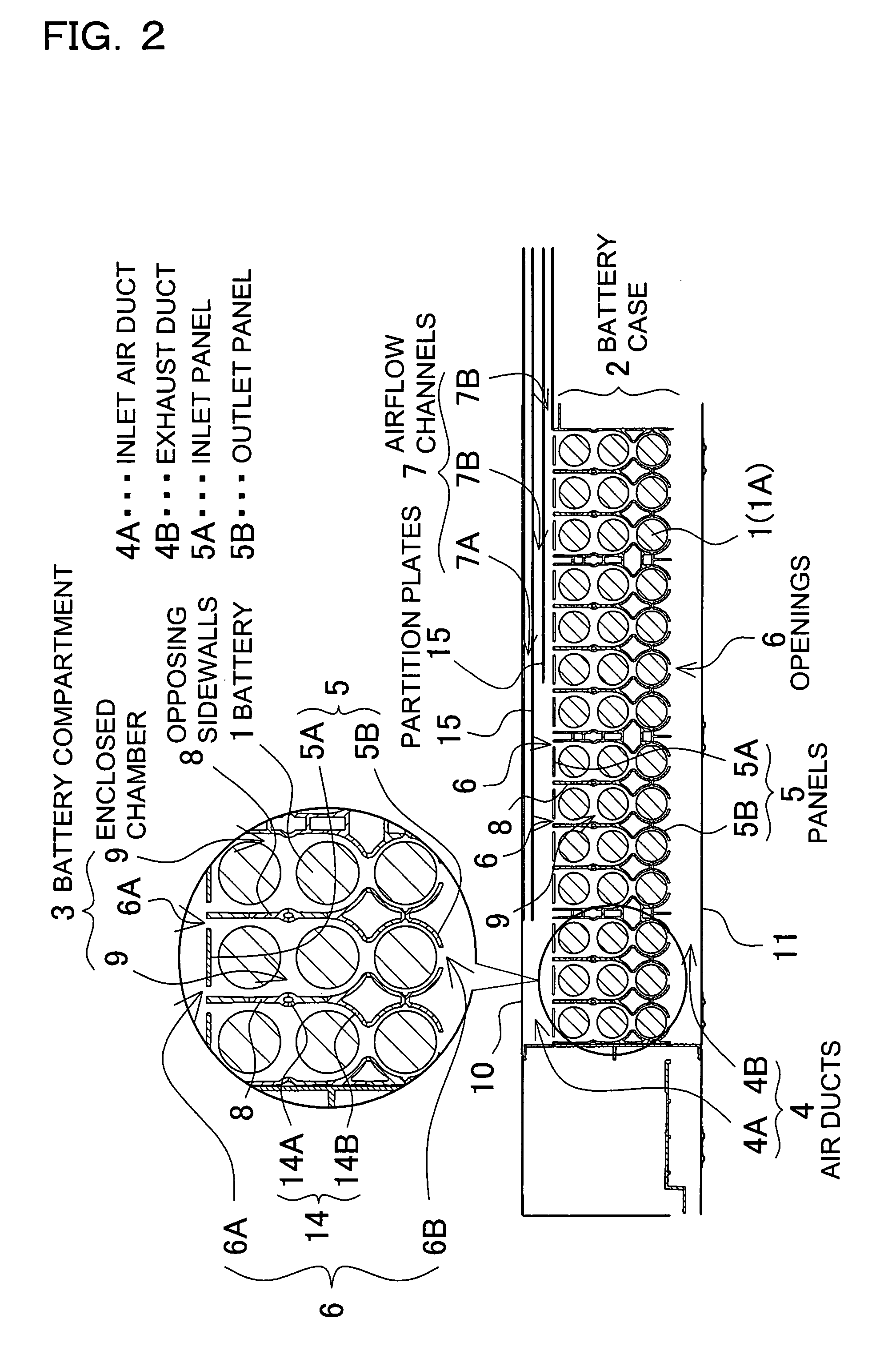
[0011]The car power source apparatus of the present invention has the following structure to achieve the object above. The car power source apparatus is provided with a battery case housing a plurality of rechargeable batteries in a battery compartment, and air ducts to carry ventilating air to the battery case and cool the batteries. A plurality of air inlet and outlet openings are provided through panels between the battery compartment and the air ducts. Inlet and outlet openings are opened in a direction different from the direction of airflow in the ducts. Air is passed through those openings to cool the batteries from an air duct into the battery compartment, or from the battery compartment to an air duct. In addition, the power source apparatus has a plurality of airflow channels of differing length established inside an air duct in the direction of airflow. This divides ventilating airflow in the air duct into a plurality of airflow channels. The power source apparatus above has the characteristic that airflow in an air duct can be uniformly distributed in the direction of airflow to ventilate the battery compartment and uniformly cool batteries housed in the battery compartment. This is because a plurality of airflow channels, having different lengths in the direction of flow, are established to partition the inside of the air duct, and ventilating air in the duct is divided into those airflow channels to allow uniform flow through a plurality of battery compartment inlet and outlet openings. In a power source apparatus with this configuration, the opening at the end of an airflow channel can be established next to a battery compartment inlet opening with reduced airflow to increase airflow to that inlet opening. For example, in the case where an inlet opening at the extreme interior of the air duct has a reduced quantity of airflow, the opening at the end of an airflow channel can be disposed at the extreme interior of the duct, and the quantity of airflow to that inlet opening can be increased.

Problems solved by technology

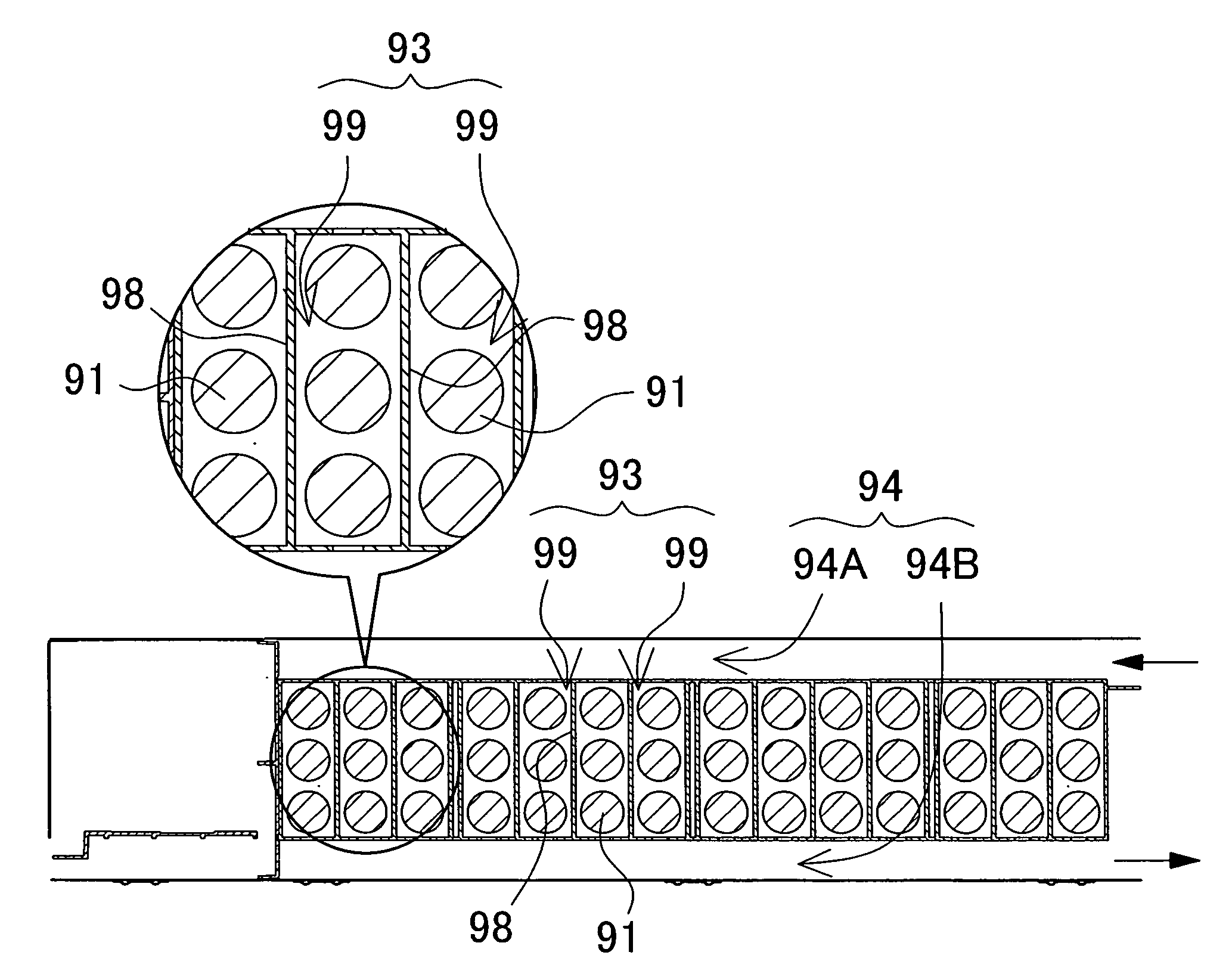
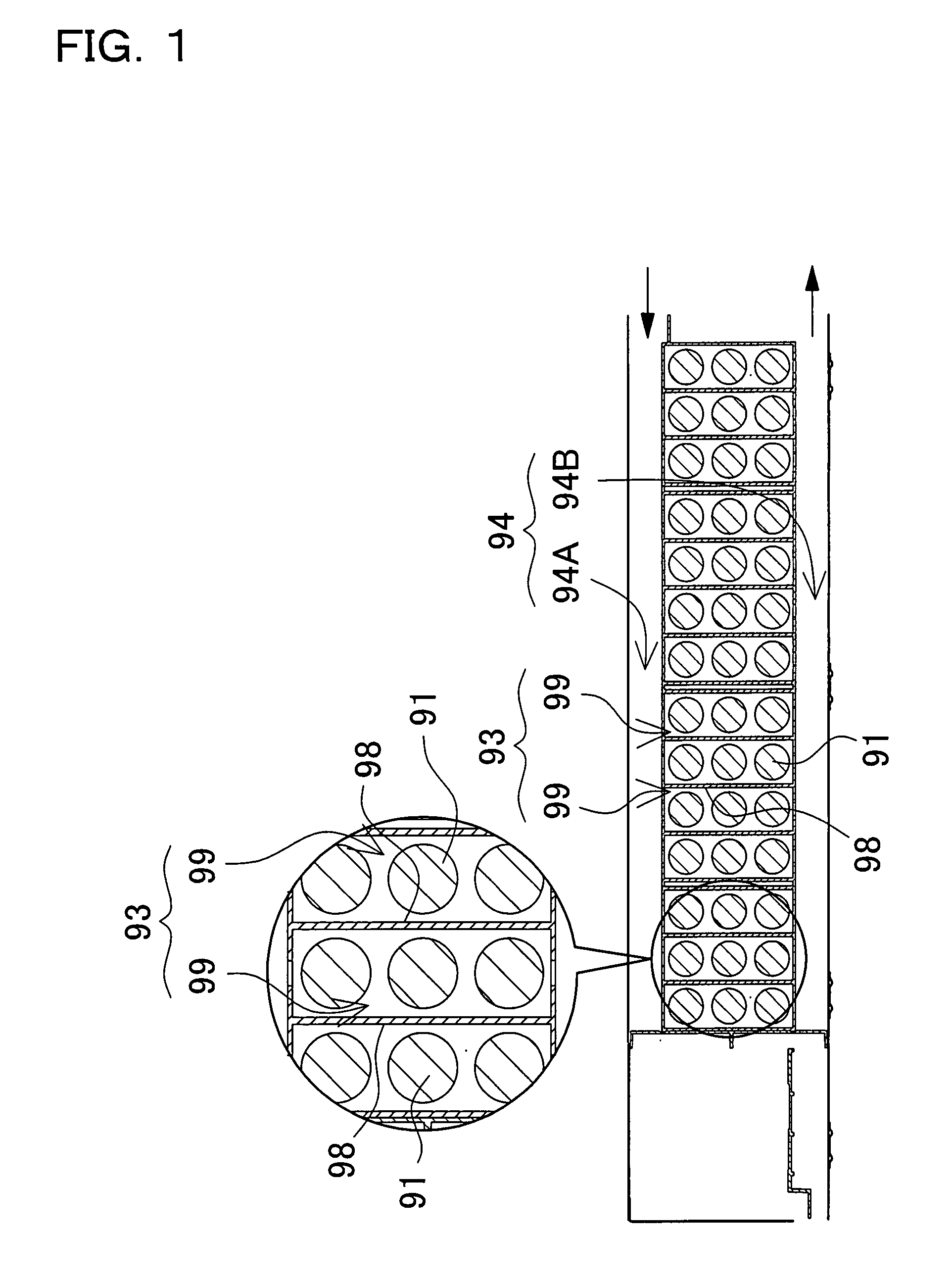
However, the flow of ventilating air cannot be uniformly distributed to cool the batteries simply by a configuration that reduces air duct width in the direction of ventilating airflow.

Method used


Image

  • Car power source apparatus
  • Car power source apparatus
  • Car power source apparatus

Examples


Embodiment Construction

[0021]The following describes embodiments of the present invention referring to the drawings. However, the following embodiments are intended as examples of a car power source apparatus to make tangible the underlying technological ideas of the invention, and the car power source apparatus of the present invention is in no way specified by the following.

[0022]Further, in this application, part numbers indicated in the embodiments are also noted in the claims (and summary of the invention) to make the claims easier to understand. However, parts of the invention indicated in the claims are in no way restricted to the parts described in the embodiments.

[0023]The power source apparatus shown in FIGS. 2 and 3 houses a plurality of batteries 1 in the battery compartment 3 of a battery case 2. Batteries 1 are housed in the battery case 2 as battery modules 1A. A battery module 1A is a series connection of a plurality of individual battery cells joined in a straight-line fashion. For exampl...


PUM


Abstract

The car power source apparatus is provided with a battery case housing a plurality of rechargeable batteries in a battery compartment, and air ducts to carry ventilating air to the battery case and cool the batteries. A plurality of air inlet and outlet openings are provided through panels between the battery compartment and the air ducts. Air inlet and outlet openings are opened in a direction different from the direction of airflow in the ducts. Further, the power source apparatus has a plurality of airflow channels of differing length established inside an air duct in the direction of airflow. This divides ventilating airflow in the air duct into a plurality of airflow channels.

Description

BACKGROUND OF THE INVENTION[0001]1. Field of the Invention[0002]This invention relates to a car power source apparatus that cools batteries housed in a battery case by flowing air through ventilation ducts.[0003]2. Description of the Related Art[0004]An electric vehicle such as an electric automobile or a hybrid car, which is powered by both an internal combustion engine and an electric motor, uses a power source apparatus as a source of electric power to supply to a driving motor (or motors). The power source apparatus has many connected individual battery cells housed in a battery case.[0005]A power source apparatus used in this type of application should establish high output voltage to supply power to a high output motor. Consequently, many individual battery cells are connected in series and housed in a battery case. For example, a power source apparatus installed in a hybrid car currently on the market connects several hundred individual battery cells in series to produce an o...

Claims


Application Information

Patent Timeline
IPC IPC(8): B60H1/00B60K11/06H01M10/613H01M10/60H01M10/625H01M10/6557H01M10/6563H01M10/6566H01M50/213H01M50/271
CPCH01M2/1077H01M10/052H01M10/345H01M10/5004H01M10/5016Y02T10/7011H01M10/5038H01M10/5059H01M10/5067H01M10/5073H01M10/5036H01M10/625H01M10/6563H01M10/652H01M10/6557H01M10/6566H01M10/651H01M10/613Y02E60/10H01M50/213H01M50/271H01M50/249H01M50/258B60L58/26B60L50/64H01M2220/20
Inventor SHIMIZU, HIDEOKOMAKI, TSUYOSHIFUJII, KAZUHIRO
Owner SANYO ELECTRIC CO LTD
Learn More