
Imaging system and method including multiple, sequentially exposed image sensors

Inactive Publication Date: 2007-08-30
ACCU SPORT INT
View PDF3 Cites 3 Cited by
  • Summary
  • Abstract
  • Description
  • Claims
  • Application Information

AI Technical Summary

Benefits of technology

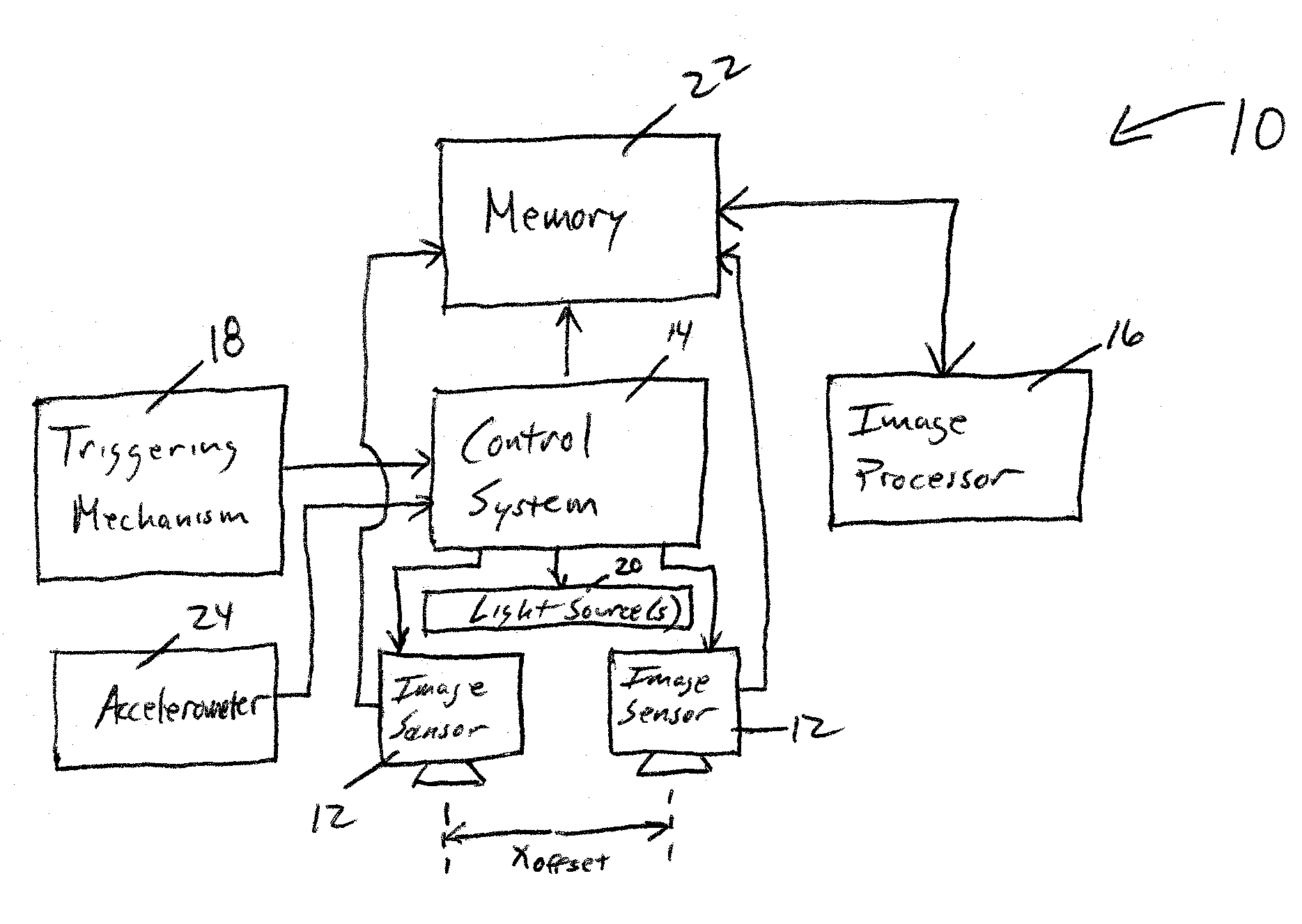
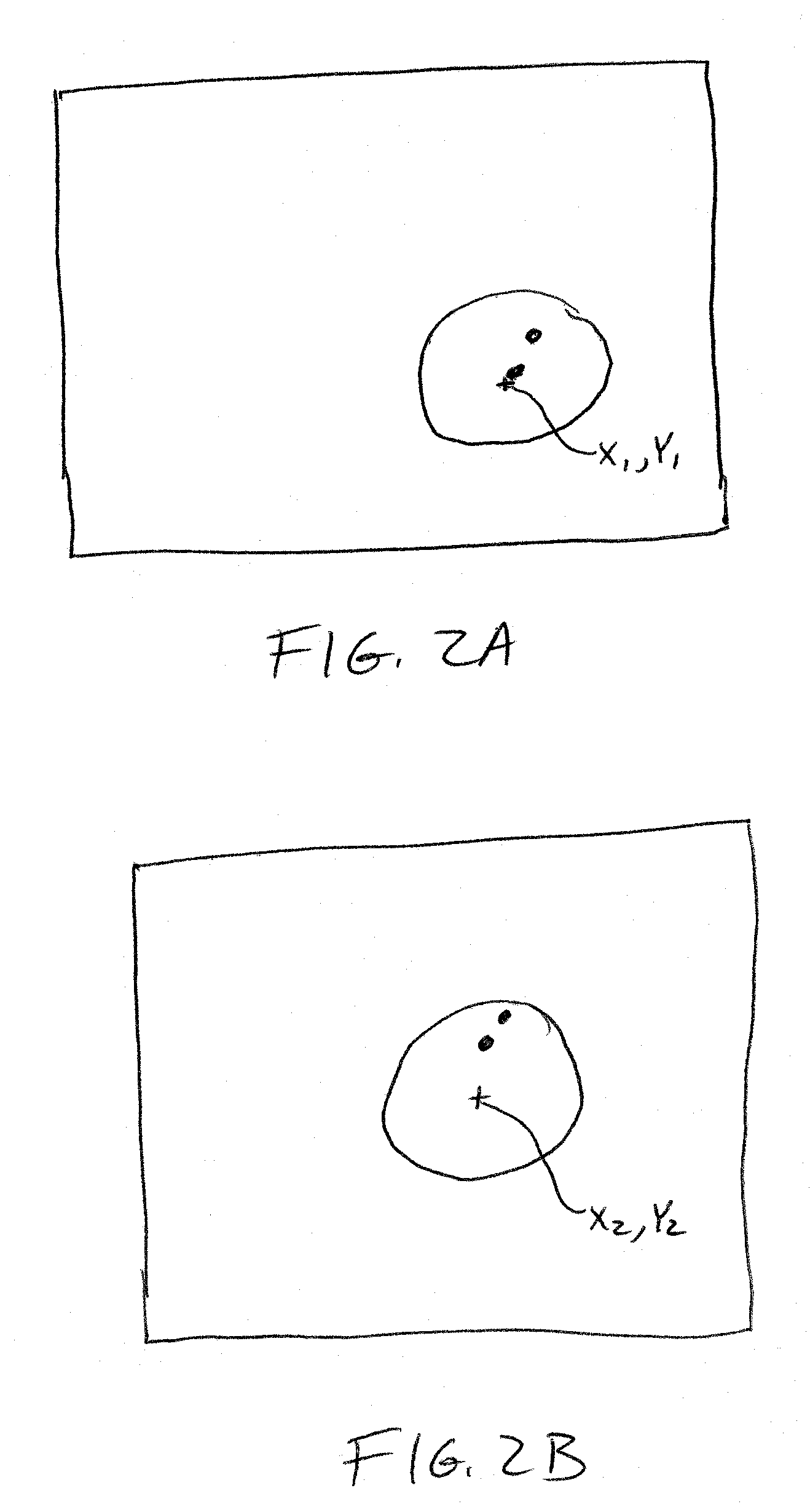
[0011] An imaging system and method are therefore provided to address at least some of the issues of conventional imaging systems. For example, an imaging system and method of one embodiment are capable of determining a plurality of parameters associated with movement of a ball based upon single exposure images captured by a plurality of image sensors, thereby potentially reducing the power required to operate the system and improving the resolution of the images and, in turn, the accuracy with which the parameters are determined. By way of another example, an imaging system and method of another embodiment are capable of automatically compensating for changes in orientation of an image sensor from a predefined orientation such that the resulting parameters that define the movement of the ball are potentially determined in a more accurate fashion.

Problems solved by technology

While this technique is quite workable and provides accurate results, the image captured by the camera can be adversely affected by the ambient lighting conditions since the shutter remains open for relatively long period of time while the strobes are pulsed on two occasions.
The ambient light that is received while the shutter is open tends to decrease the resolution and the contrast of the images of the golf ball that are otherwise captured by the camera.
This decreased resolution can adversely affect the accuracy with which the resulting golf ball launch parameters are determined.
However, the cost of the resulting launch monitor is increased as more powerful strobe lights are utilized.
Additionally, the power consumption of the launch monitor is increased as more powerful strobe lights are employed.
While cameras are available that can capture the successive images such cameras are typically quite expensive so as to adversely affect the cost of the resulting golf ball launch monitor.
However, it is generally quite difficult to ensure that the launch monitor is disposed in the same orientation with the orientation of the launch monitor generally changing by at least a degree or two from one location to the next.
However, users may have difficulty in accurately determining the offset to be entered or users may simply forget to enter the offset.
In instances in which the user forgets to enter the offset or enters an incorrect offset, some of the resulting parameters, such as the launch angle of the golf ball, that are determined by the launch monitor will be correspondingly inaccurate.

Method used


Image

  • Imaging system and method including multiple, sequentially exposed image sensors
  • Imaging system and method including multiple, sequentially exposed image sensors
  • Imaging system and method including multiple, sequentially exposed image sensors

Examples


Embodiment Construction

[0022] The present inventions now will be described more fully hereinafter with reference to the accompanying drawings, in which some, but not all embodiments of the inventions are shown. Indeed, these inventions may be embodied in many different forms and should not be construed as limited to the embodiments set forth herein; rather, these embodiments are provided so that this disclosure will satisfy applicable legal requirements. Like numbers refer to like elements throughout.

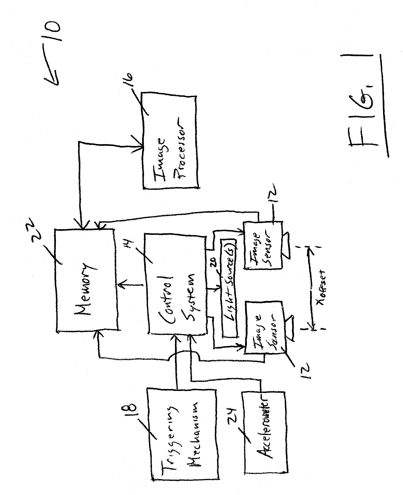
[0023] As shown in FIG. 1, the imaging system 10 of one advantageous embodiment of the present invention includes at least two image sensors 12 operating under the direction of a control system 14, such as a microcontroller, microprocessor, personal computer or other computing system. While various types of image sensors may be utilized, the imaging system of one embodiment includes image sensors that are of an accumulator type, such as image sensors that are each comprised of a plurality of CCDs arranged in...


PUM


Abstract

An imaging system and method are provided that include one or more image sensors, a light source for illuminating the field(s) of view of the image sensor(s), a control system for directing operation of the light source and the image sensor(s) in order to capture image(s) of a ball and an image processor for analyzing the image(s) of the ball to determine at least one parameter associated with movement of the ball through the field(s) of view of the image sensor(s). An imaging system and method of one aspect are capable of determining a plurality of parameters associated with movement of a ball based upon single exposure images captured by a plurality of image, while an imaging system and method of another aspect include an accelerometer and are capable of automatically compensating for changes in orientation of an image sensor from a predefined orientation.

Description

CROSS REFERENCE TO RELATED APPLICATION(S) [0001] The present application claims priority to U.S. Provisional Application No. 60 / 761,119, filed Jan. 23, 2006 entitled Imaging System and Method Including Multiple, Sequentially mage Sensors, the contents of which are incorporated herein in their entirety.FIELD OF THE INVENTION [0002] Embodiments of the present invention relate generally to techniques for measuring the launch conditions of a golf ball or other object in motion and, more particularly, to techniques for capturing successive images of a golf ball or other object from which a variety of launch parameters can be determined. BACKGROUND OF THE INVENTION [0003] Many golfers work consistently to improve their game. One tool that has been developed to assist golfers in analyzing their golf shots is a golf ball launch monitor. Golf ball launch monitors are used extensively to provide detailed information regarding the velocity of the ball, the launch angle of the ball, the side sp...

Claims


Application Information

Patent Timeline
IPC IPC(8): A63B69/36
CPCA63B24/0003G06T2207/30224A63B69/0002A63B69/3658A63B69/3676A63B69/38A63B2024/0028A63B2024/0031A63B2024/0034A63B2220/05A63B2220/18A63B2220/30A63B2220/35A63B2220/40A63B2220/805A63B2220/807A63B2243/0029G06T7/20A63B24/0021A63B2102/32
Inventor RANKIN, DAVID B.
Owner ACCU SPORT INT
Learn More